Solar LED Lantern Circuit is small setup using sun power to give light with LED.
It have solar panel through which the battery charges again to LED lights and some small parts like diode, resistor and transistor.
Circuit Working:
Parts List:
| Type | Value | Quantity |
|---|---|---|
| Resistors | 15Ω 1/2W | 1 |
| 1.5Ω 1/2W | 1 | |
| 1k 1/4W | 2 | |
| Semiconductors | Transistor BC547 | 1 |
| Transistor 2N2222 | 1 | |
| Diode 1N4007 | 1 | |
| LEDs white straw hat 5mm | 20 | |
| Battery 3.7V 800mAh | 1 | |
| ON/OFF Switch | 1 | |
| Solar panel 6V 5W | 1 |
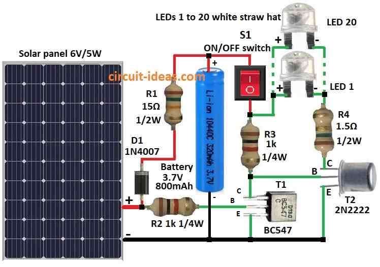
This solar LED lantern circuit uses 6V 1W solar panel and small 4V 800mAh lead acid battery.
It use normal 5mm white straw hat LEDs for light.
Solar panel gives 6V DC and charge battery through one diode D1 1N4007 and resistor R1 15 ohm.
Diode D1 stop current going back and R1 make charging current safe which is not too high.
Transistor T1 BC547 work like auto switch as it control another transistor T2 2N2222 which drive LED.
When sun power is enough T1 stop T2 and so LED does not turn ON in daytime.
Switch S1 is simple ON/OFF switch.
Resistor R4 control how much current connects to LED group.
Solar panel does not have load voltage which is around 7.2V and it give near 170mA at 6V when sunlight is okay.
Battery is full charge and gives about 4.6V when there is no load.
The 5mm white straw hat LED need 3 to 3.2V to turn ON and it can take 20mA always with max 30mA short time as per the datasheet.
Formulas:
Formula for Li-ion Battery Backup Time:
Backup time (hours) = (Battery capacity (Ah) × Battery voltage (V) × Battery efficiency) ÷ Load current (A)
Explanation:
- Battery capacity in Ah tell how much charge battery can hold.
- Battery voltage V is normal battery voltage.
- Battery efficiency mean some power lost when charging/discharging is mostly 90% to 95%.
- Load current A is how much current device is using from battery.
Important Things:
This formula give only rough idea not exact time.
Real backup time can change because of battery getting old, different load or temperature.
For more accurate result we should check discharge curve of battery as it show how voltage goes down when battery is using power.
Always check battery datasheet for correct information and real specification.
How to build:
To build a Solar LED Lantern Circuit follow the below mentioned assembling steps:
- Connect solar panel positive wire to diode D1 1N4007 anode side.
- Connect negative wire of solar panel to battery negative terminal.
- Connect cathode side of diode D1 to one side of resistor R1 15 ohm
- Then connect other side of R1 to positive terminal of battery.
- Connect battery negative to solar panel negative.
- Connect transistor T1 BC547 like auto switch.
- Connect T1 collector to battery positive.
- T1 emitter connects to collector of transistor T2 2N2222.
- T1 base connects to a point that can sense solar panel voltage.
- Connect anode positive leg of each LED to collector of T2.
- Join all LED cathodes negative legs together.
- Put resistor R4 in series with LEDs to limit current.
- Connect switch S1 in series with battery positive wire to turn circuit ON/OFF.
- Be sure all wires and parts are connected good.
- Use tape or cover to stop short circuit.
- Put solar panel in sunlight which is not too strong and check if LEDs turn ON.
- Change resistor value if light is not bright enough or too bright.
Note:
- Be careful while working with electricity is not safe if we not know well.
- Ask help from someone who know electronics or talk to expert.
Conclusion:
A Solar LED Lantern Circuit is cheap and eco-friendly light idea which uses sunlight to give power to LEDs.
It have solar panel through which the battery charges again to some LEDs and small parts to control power.
This circuit gives light in places where there is no electricity so it is useful and good for environment.