In this post for How to Illuminate 18 LEDs from a 3.7V Battery we need to power 18 LEDs with 3.7V battery like a small light party!
Also, to light all LEDs well we need smart plan; we have to make small LED groups and connect in clever way.
So use series in line and parallel in row and this will control voltage and current and then LEDs will shine bright without any burn.
Circuit Working:
Parts List:
| Components | Values | Quantity |
|---|---|---|
| Resistors | 1k, 10Ω (1/4 watt) | 1 each |
| 10k (1/4 watt) | 2 | |
| Capacitors | Ceramic 10nF | 1 |
| Electrolytic 100μF 25V | 1 | |
| Semiconductors | Transistors BC547, 2N2222 | 1 each |
| Inductor 1mH | 1 | |
| LEDs white straw hat 5mm, 20mA | 18 | |
| ON/OFF switch | 1 | |
| Li-ion Battery 3.7V | 1 |
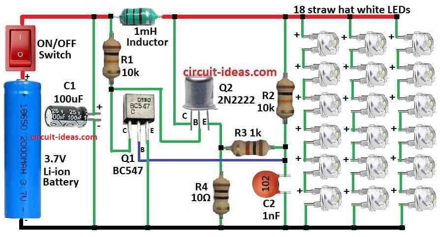
This circuit uses a 3.7V Li-Ion battery to light 18 white LEDs, additionally, it uses components rescued from an old CFL lamp, also, the circuit uses two transistors, such as 2N2222 and BC547, to keep the LED brightness consistent at all times.
Here, BC547 give feedback to keep circuit working and even with high 10k resistor it rans 12 hours on 1200mAh battery and brightness stay steady.
Furthermore, 2N2222 transistor control how bright LEDs shine, it get small current from 10k resistor but because of gain from 100 to 300 the output current goes up to 100mA.
Then LEDs run slightly over limit but BC547 help control it and turn OFF 2N2222 at right time so it does not stay ON too long; after that, 10k and 1k resistors make voltage divider to set timing.
When 2N2222 turn ON, 10 ohm resistor makes voltage that delays turns ON a bit and 1nF capacitor set how fast circuit oscillates which turns ON/ OFF
Therefore, by changing these four parts like resistors and capacitor we can get and keep the right brightness for whole battery life.
LEDs in each string are in series and for even brightness all strings must match and we can also swap LEDs to balance the brightness.
Formulas:
Using boost converter and we can increase 3.7V battery to higher voltage for 18 LEDs in series or parallel.
Important boost converter formulas:
1. Output Voltage (Vout):
Vout = Vin / (1 − D)
- Vin is the input voltage for 3.7V
- D is the duty cycle for how long switch is ON
2. Inductor Current (IL):
IL = Vout × D × T / L
- T is the time of one switch cycle
- L is the inductor value
3. Duty Cycle (D):
D = (Vout − Vin) / Vout
4. Choose Inductor (L):
L ≥ (Vout − Vin) × Vout / (f × ΔIL)
where,
- f is the switch frequency
- ΔIL is the ripple current in inductor
Hence, these formulas help design good boost converter and with this we can light up 18 LEDs using 3.7V battery; but ensure to check LED forward voltage to match circuit design.
How to Build:
How to Illuminate 18 LEDs from a 3.7V Battery find out the below mentioned steps for connection of components.
- First, connect batteries positive (+) to positive supply line through an ON/OFF switch and then connect batteries negative (–) to ground.
- After that, connect collector of transistor Q1 to positive supply through resistor R1, connect base of Q1 between resistor R2 and capacitor C2 and then connect emitter of Q1 to ground.
- Now connect capacitor C1 from positive supply to ground for power smoothing and place a 1mH inductor between R1 and collector of Q2 in the positive line.
- Next, connect collector of Q2 to positive supply, connect base of Q2 between R1 and collector of Q1 and then connect emitter of Q2 to ground through resistor R4.
- Then connect resistor R3 between R2 and C2.
- Finally, connect 18 straw hat white LEDs in series from positive supply to ground as shown in the circuit diagram above.
Important Notes:
- Cover circuit well to avoid short circuits; always use current limiting resistors to protect LEDs and remember too much current can overheat and damage LEDs.
Conclusion:
To conclude, this article explained How to Illuminate 18 LEDs from a 3.7V Battery through a smart circuit design that matches the required voltage and current; consequently, the circuit provides bright light while reducing power loss.
Leave a Reply