Mobile phones need charging every day.
In remote areas power is not always there.
Solar charger is best option.
Sunlight is free and always available in day.
Small solar panels can make a charger for phone.
This project is about Simple Solar Mobile Charger Circuit
Circuit Working:
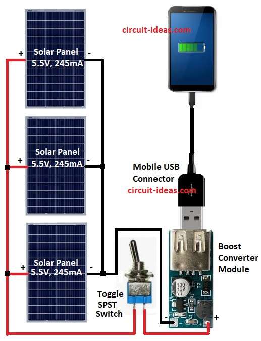
Parts List:
| Component | Specification | Quantity |
|---|---|---|
| Solar Panel | 5.5V, 245mA | 3 |
| Boost Converter Module | 5V Output | 1 |
| Switch | Toggle SPST | 1 |
| USB Pin / USB Connector | Standard USB | 1 |
As per the above circuit diagram three solar panels are used.
Each panel is 5.5V 245mA.
Panels are connected in parallel.
Parallel connection gives same voltage 5.5V but adds current.
Total current is 245mA + 245mA + 245mA = 735mA.
Output goes to USB port through switch.
Phone charges from USB port.
Formulas with Calculations:
Below mentioned is the formula for Simple Solar Mobile Charger Circuit:
Panel voltage = 5.5V (constant in parallel)
Panel current = 245mA
Total current = 3 panels × 245mA = 735mA
Output power = Voltage × Current = 5.5V × 0.735A = 4.04W approx.
This is enough for charging a normal phone.
How to Build:
To build a Simple Solar Mobile Charger Circuit following are the connections steps:
- Gather all parts like in circuit.
- Join positive pins of three solar panels together.
- Join negative pins of three solar panels together.
- Common positive goes to one side of switch.
- Other side of switch goes to boost converter VIN+.
- Common negative goes to boost converter VIN–.
- Connect USB wire to USB socket for mobile charging.
Conclusion:
This Simple Solar Mobile Charger Circuit is easy to make.
It gives free power from sun.
It is small, safe and useful for phone charging.
Good project for students and beginners.
Leave a Reply