Imagine our voice is strong but we whisper through a tiny straw to reach our far friend but it wont work.
Same is in circuit for Simple Speaker Audio Output Transformer Circuit which works like a megaphone for sound signal.
It takes strong signal from amplifier and changes it to fit the speaker so music sounds clear and powerful, just like we want.
Circuit Working:
Parts List:
| Category | Item | Quantity |
|---|---|---|
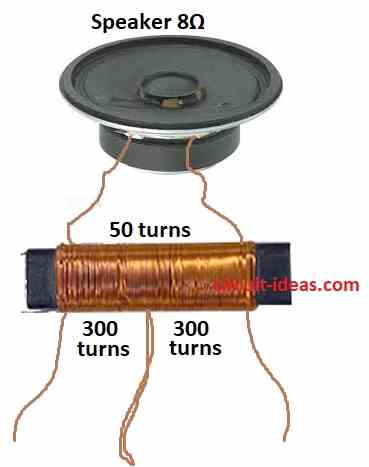
| Semiconductors | 8Ω Speaker | 1 |
| Ferrite Rod coil (see text) | 1 |
The diagram shows the transformer is important to connect speaker to the circuit.
It is made by winding thin wire on a ferrite rod.
Transformer works based on wire turns and not with the rod size.
How to make it:
Secondary Winding: First wind 50 turns of thick 0.25mm wire on the rod.
Primary Winding: Then wind 300 turns of thin 0.1mm wire on top and make a center loop with center tap.
Add 300 more turns of the same thin wire to finish.
Connections does not matter:
It is okay to connect speaker wires to top or bottom and sound stays the same.
Same for primary and either end can connect to the transistor collector.
Formulas:
From the diagram this is the formula for transformer turns ratio:
Turns Ratio (n) = Np / Ns
where:
- n is the ratio of turns with no units
- Np is the number of turns in primary coil
- Ns is the number of turns in secondary coil
This ratio controls voltage difference between coils.
How it works:
If n > 1 Np more than Ns its a step-up transformer.
If voltage is in secondary Vs is higher:
Vs = Vp × n
If n < 1 Np is less than Ns, its a step-down transformer.
Voltage is in secondary is lower:
Vs = Vp / n
Important:
In perfect transformer:
Vp × Ip = Vs × Is
where:
- Vp is the primary voltage
- Ip is the primary current
- Vs is the secondary voltage
- Is is the secondary current
Real transformers lose some power like core + wire losses.
Efficiency is 90% to 99%.
Turns ratio is used to step up or step down voltage in circuits.
Conclusion:
Simple Speaker Audio Output Transformer Circuit were important in old amplifier designs.
They helped match amplifier to speaker for best sound.
They fixed impedance mismatch and blocked bad DC current.
Now modern amps do not need them much but they are still cool parts in audio history.
References:
Can an ordinary transformer be used for coupling the speaker with a transistor amplifier
Leave a Reply