Blind people have big problem on road because they cannot see object in front; so to solve this we made an Ultrasonic Blind Stick Circuit using Arduino
The stick actively senses objects and uses a buzzer to warn a blind person with sound.
We can build this low cost project easily using components such as an Arduino Nano, an ultrasonic sensor, a buzzer, a switch and a battery.
Arduino Code:
#include <NewPing.h>

#define TRIGGER_PIN D3
#define ECHO_PIN D2
#define BUZZER D8
#define MAX_DISTANCE 200

NewPing sonar(TRIGGER_PIN, ECHO_PIN, MAX_DISTANCE);

void setup() {
pinMode(BUZZER, OUTPUT);
Serial.begin(9600);
}

void loop() {
delay(50);
unsigned int distance = sonar.ping_cm();
Serial.print("Distance: ");
Serial.print(distance);
Serial.println("cm");
if (distance > 0 && distance < 50) {
digitalWrite(BUZZER, HIGH);
} else {
digitalWrite(BUZZER, LOW);
}
}
Code Explanation:
- We use NewPing library for ultrasonic sensor.
- We set pins for trigger, echo and buzzer.
- In the setup, the code sets the buzzer as an output and starts the serial monitor.
- In loop we read distance from sensor with sonar.ping_cm() which gives distance in cm.
- If object is less than 50 cm then buzzer turns ON and make sound.
- If there is no object or more distance then buzzer is OFF.
- We add 50 ms delay for stable reading.
Circuit Working:
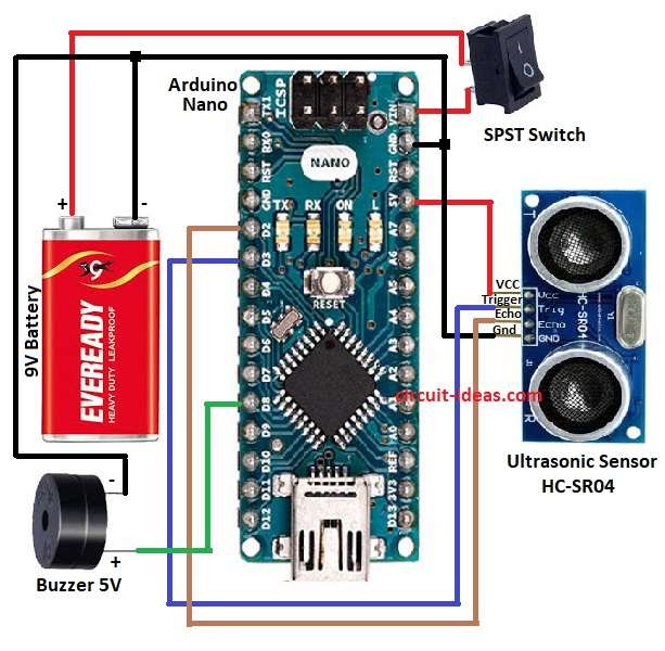
Parts List:
| Components | Values | Quantity |
|---|---|---|
| Arduino Nano | ATmega328P | 1 |
| Ultrasonic Sensor | HC SR04 | 1 |
| Buzzer | 5 Volt | 1 |
| Switch | SPST | 1 |
| Battery | 9 Volt | 1 |
To begin with, the main aim of this project is to help blind people walk safe and easy.
When object or person blocks the way the circuit makes buzzer sound and then buzzer sound changes with distance.
If object is near then buzzer beep fast and if object is far then buzzer beep slow and so buzzer speed is opposite to distance.
In this circuit we used Arduino Nano as brain and ultrasonic sensor send sound wave and check distance of object.
Sensor have 4 pins Vcc, Gnd, Trigger, Echo.
Trigger send sound and Echo get back sound and then Arduino count time and find the distance and if object is close than set a range and Arduino turns ON buzzer and buzzer makes sound.
Formulas and Calculations:
Ultrasonic sensor work with speed of sound.
Distance formula is: Distance = (Time x Speed of Sound) / 2
Speed of sound is 343 meter per second and we have divide by 2 because sound go to object and come back.
Example: if echo time is 2 millisecond then distance = (0.002 x 343) / 2 = 0.343 meter.
Arduino uses pulse in function to measure time in microsecond.
How to Build:
To build a Ultrasonic Blind Stick Circuit using Arduino follow below steps for connection:
- First, collect all parts like in circuit diagram.
- Next, Arduino Nano Vcc goes to 5V and Gnd goes to battery negative.
- Sensor Vcc goes to Arduino 5V and sensor Gnd goes to Arduino Gnd.
- Sensor Trigger connect to D3 and Echo connect to D2 of Arduino.
- Buzzer positive connect to D8 and buzzer negative to Gnd.
- 9V battery connect to Vin of Arduino Nano and negative of battery connects to Arduino Nano GND
- SPST switch connects to positive of 9V battery
Conclusion:
To conclude, this project for Ultrasonic Blind Stick Circuit using Arduino is simple but very helpful for blind people; it gives warning sound when any obstacle is in front of them.
The circuit is low-cost and easy for anyone to build, hence, users can further improve it by adding a vibration motor or GPS to create a smarter stick.

Leave a Reply