Humidity is presence of water vapor in air or soil, also too much or too less humidity is harmful for plants and for storage; so we need a Simple Humidity Level Detector Circuit.
This small circuit uses only a few components and provides an LED indication when the humidity crosses a preset level and we can also use it to test soil moisture.
Circuit Working:
Parts List:
| Components | Description |
|---|---|
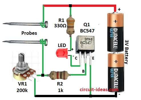
| Resistors | 330 ohms 1/4 watt |
| 1k ohms 1/4 watt | |
| Potentiometer 200k | |
| Semiconductors | Transistor BC547 |
| Battery 3V | |
| LED any color | |
| Any iron nail, pin clip or metal wires as probes |
Many humidity tester circuits are there, but this one is very simple and its working is easy to understand.
The circuit uses only one transistor, one LED and a few resistors, also it can test humidity levels in soil, paper, and other materials.
When humidity increases the material conducts more current and this current goes through VR1 and if voltage across VR1 becomes 0.7V then transistor turns ON and LED glows.
Then, potentiometer VR1 adjusts the sensitivity, then turning the knob changes the resistance and shows the humidity level required to switch the transistor ON.
R1 limits the LED current and protects the transistor when the probes short together and to set up the circuit, place the probes in the sample and adjust VR1 until the LED just glows.
After that, whenever the sample reaches the selected humidity level, the LED glows.
Also, insert two metallic wires into the soil as probes, and note that the distance between the probes affects the sensitivity.
Finally, this circuit runs on 3V battery.
Formulas and Calculations:
Following are the simple formulas for Humidity Level Detector Circuit.
Transistor BC547 needs base current (Ib) to turn ON.
Ib = Ic / hFE
where,
- Ic is collector current
- hFE is current gain which is normally 100 to 200 for BC547.
LED current needed around 5mA to 10mA.
So if Ic = 10mA and hFE = 100
Ib = Ic / hFE = 10mA / 100 = 0.1mA
So probes and resistor R2 and VR1 must allow at least 0.1mA current at humidity condition; also, with 3V supply and R2 is 1k then maximum base current possible is around 3mA which is enough to drive a LED.
How to Build:
To build a Simple Humidity Level Detector Circuit follow the below steps for connections and assembling:
- First, take all the parts as shown in circuit diagram
- Next, connect transistor Q1 collector pin to LED and R1 resistor.
- Then connect transistor Q1 base pin to probe via R2 resistor and potentiometer VR1
- Now connect transistor Q1 emitter pin to battery negative
- Then, connect one end of the probes to the positive supply of the 3V battery and connect the other end to resistor R2 and potentiometer VR1.
Conclusion:
Simple Humidity Level Detector Circuit is easy and useful circuit to detect moisture in air, as it uses few components and gives indication when humidity level changes.
Also, this circuit is good for home, garden and small monitoring projects.
Leave a Reply