Sometimes, people forget to close the fridge door and this causes loss of cooling and waste of electricity; so to solve this problem we can use a simple Refrigerator Door Open Alarm Circuit with IC 555
When the door stays open, the buzzer gives a sound, so it reminds the user to close the doo; also this project uses two 555 timer ICs, LDR and a few passive components as it is small, cheap and can run from 3V battery.
Circuit Working:
Parts List:
| Components | Values | Qty |
|---|---|---|
| Resistors (All resistors are 1/4 watt unless specified) | 10k | 1 |
| 2.2M | 1 | |
| 1M | 1 | |
| LDR | 1 | |
| Capacitors | Ceramic 100nF | 1 |
| Electrolytic 10µF 25V | 1 | |
| Semiconductors | IC 555 | 2 |
| Diode 1N4001 | 1 | |
| Piezo Buzzer | 1 | |
| Battery 3V | 1 |
Here, the refrigerator door alarm circuit explains with simple working.
Main aim of this circuit is to give buzzer sound when fridge door stays open for more than a set time.
The circuit uses two 555 timer ICs and both 555 ICs work as oscillators, moreover the circuit uses an LDR as the sensor and it is a light-sensitive device.
In dark condition, it has high resistance, however when light falls on it the resistance becomes low and therefore this change triggers the alarm and also the LDR connects with the timing capacitor C1 of IC1.
When the fridge door closes the inside light turns OFF and the LDR keeps high resistance so the capacitor charges normally.
However, when the door stays open the lamp glows and the LDR resistance drops and as a result, the capacitor stops charging and then starts discharging.
This action makes IC1 start the timing and after around 25 sec IC1 output goes high.
This output enables IC2, which then oscillates and drives the buzzer to produce a beeping sound, the cycle repeats until the door closes.
We can change the time delay by adjusting the values of R and C, also refer to the 555 timer datasheet to show the appropriate values for the required delay.
Place LDR close to fridge lamp for best result.
How to Build:
To build a Refrigerator Door Open Alarm Circuit with IC 555 follow below steps for connection:
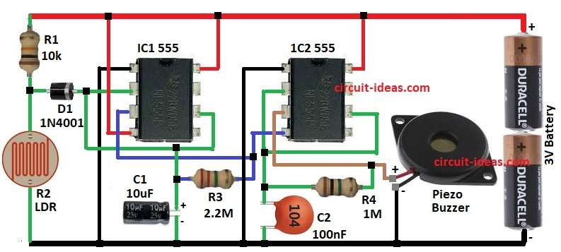
- First, gather all the components as shown in circuit diagram
Connection of IC1:
- Next, connect pin 1 of 1C1 555 to GND of the circuit
- Then connect pin 2 of IC1 to LDR and diode
- After that connect pin 3 of IC1 to pin 4 of IC2
- Connect pin 4 and pin 8 of IC1 to positive supply of 3V
- Then connect pin 6 of IC1 to pin 2 of IC1
- Also, connect diode D1 between the junctions of resistor R1 and LDR R2
Connection of IC2:
- Next, connect pin 1 of 1C2 555 to GND of the circuit
- Then connect pin 2 and pin 6 of IC2
- After that, connect pin 3 of IC2 to output of the buzzer one end and other end of buzzer goes to GND
- Connect pin 4 and pin 8 of IC2 to positive supply of 3V
- Connect resistor R3 between the junction of pin 3 and pin 2 of IC1
- Connect resistor R4 between the junction of pin 3 and pin 2 of IC2
- Also, connect capacitor C1 one end to resistor R3 and pin 2 of IC1 and other end to GND
- Finally, connect capacitor C2 one end to resistor R4 and pin 2 of IC2 and other end to GND
Conclusion:
To conclude, this Refrigerator Door Open Alarm Circuit with IC 555 is very easy to make as it prevents electricity loss and keeps food fresh by reminding the user to close fridge door if they have kept it open.
A delay of around 20 to 25 seconds prevents false alarms when someone opens the door for a short time; also, the circuit uses low cost components and easy to build on small PCB.
Leave a Reply