This Timer Circuit with Alarm using IC 4060 like small stopwatch which is having buzzer inside.
It uses one chip named as IC 4060 and this chip count seconds like small clock.
We can set time how much we want. When the time finishes buzzer make sound to remind like a kitchen timer.
This circuit is good for many things like reminds to take cookie from oven or tell us to take break.
Circuit Working:
Parts List:
| Category | Component | Quantity |
|---|---|---|
| Resistors (All resistors are 1/4 watt unless specified) | 2.2M | 1 |
| 18k | 1 | |
| 1M | 1 | |
| 1k | 2 | |
| Potentiometer 500k | 1 | |
| Capacitors | Ceramic 220nF | 1 |
| Ceramic 10nF | 1 | |
| Semiconductors | IC 4060 | 1 |
| Transistor BC547 | 1 | |
| Diode 1N4148 | 1 | |
| LEDs Any 5mm 20mA | 1 | |
| Buzzer | 1 | |
| ON/OFF Switch | 1 | |
| Battery 9V | 1 |
This timer with alarm uses one chip called as 4060 and this chip have inside a small oscillator.
It work stable for many speeds.
In the circuit how fast it count is set by parts connected to pin 9, 10 and 11 which is RC network.
When we press switch S1 it starts with the timer.
One small pulse from R4 and C2 reset the chip and start counting.
When it reaches 14th step its pin 13 goes high and then buzzer turn ON with help of one transistor T1.
We can change time using P1.
To get time between 1 minute and 2 hour we must choose good parts for oscillator:
- For 1 to 30 minutes: use C1 = 220nF and P1 = 500k
- For 1 to 60 minutes: use C1 = 470nF and P1 = 500k
- For 1 to 120 minutes: use C1 = 470nF and P1 = 1M
This timer run with 9V battery.
LED D1 is only for showing its work which is not needed and R3 and D1 are optional.
If we use this in kitchen then S1 can be tilt switch with mercury.
When buzzer is ON the timer uses around 10 mA of power.
Formula:
Below is the formula for timer IC 4060 used in this circuit:
For RC Oscillator:
To find time (T) for 4060 to oscillate use this formula:
T = 2.2 × R × C
where:
- T is time in seconds
- R is resistor at pin 10 in ohms
- C is capacitor at pin 9 in farads
Important Points:
Resistor at pin 11 must be 10 times bigger than resistor at pin 10.
IC 4060 can divide time up to 2¹⁴ (16384).
So we need to think about this when choosing parts for timing.
We can check datasheet or online tables for ready made R and C values to help with setting time easily.
How to Build:
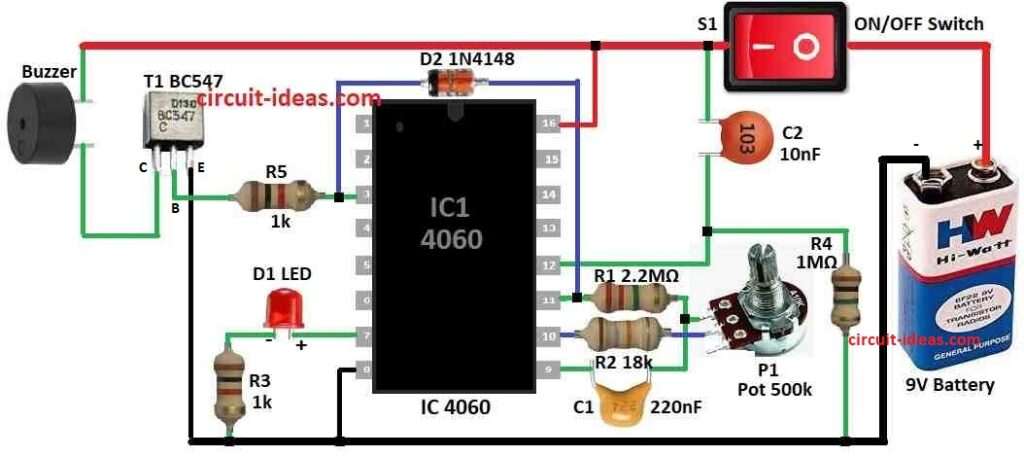
To build a Timer Circuit with Alarm using IC 4060 below are the steps for connections:
- Connect pin 9, 10 and 11 of IC 4060 to RC parts of R1, R2, C1 and P1.
- Connect pin 3 of IC to base of NPN transistor T1 and then connect emitter of T1 to ground.
- Connect collector of T1 to one side of buzzer and other side of buzzer connects to battery positive.
- Pin 16 of IC connects to positive power of VCC
- Pin 8 of IC connects to battery negative.
- Pin 7 connects to ground through resistor R3 and LED D1.
- Connect pin 11 to pin 3 using one diode D2 1N4148.
- Pin 3 also connects to middle point of R4 and C2.
- Other side of R4 connects to battery negative.
- Put switch S1 between battery positive and positive line of circuit.
- Last connect power to battery positive and negative of the circuit.
Note:
- Check if the wires are good with no short circuits
- Change P1 to set time and the circuit will work like alarm timer.
Conclusion:
This Timer Circuit with Alarm using IC 4060 is useful and works well for making alarms or timed events.
It can be build with simple design and can be used for many things like kitchen timer or small reminder alarm.
Because IC 4060 have built-in oscillator and counter the circuit gives good and steady timing.
We can also change it easy to get the time we want.