Mosquitoes are small bugs which are very annoying.
They also spread bad sickness like malaria and dengue.
This Ultrasonic Mosquito Repellent Circuit idea is to use high sound especially ultrasonic to above 20 kHz to scare mosquitoes.
Ultrasonic sound can disturb them and make them go away.
This simple circuit makes that sound.
Mosquitoes do not like this sound so they leave.
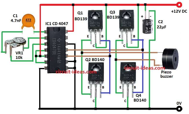
Main part is CD 4047 IC which makes high frequency sound.
Then transistors make sound stronger and piezo buzzer gives loud noise to chase mosquitoes.
Circuit Working:
Parts List:
| Component Type | Component | Quantity |
|---|---|---|
| Resistor | Preset 10k | 1 |
| Capacitors | Ceramic 4.7nF | 1 |
| Electrolytic 22µF 25V | 1 | |
| Semiconductors | IC CD 4047 | 1 |
| Transistor BD139 | 2 | |
| Transistor BD140 | 2 | |
| Piezo Buzzer | 1 |
The circuit has main parts like oscillator, transistor amplifier and piezo buzzer for sound.
Main IC is CD 4047 as it works as astable multivibrator.
This makes ultrasonic sound above 20 kHz.
VR1 and C1 set the timing for right frequency.
We can use formula to find output frequency.
To make signal stronger, 4 transistors used are used like Q1 to Q2 and Q3 to Q4.
Q1 BD139 and Q2 BD140 work in push-pull and Q3 BD139 and Q4 BD140 does the same.
These transistors make signal strong for piezo buzzer.
Then buzzer gets signal and makes sound to scare mosquitoes.
Capacitor C2 helps keep power stable and reduce noise.
Whole circuit works good with 12V DC power.
Formulas with Calculations:
Frequency Calculation:
CD 4047 gives frequency by this:
f = 1 / (4.4 × R1 × C1)
Put values:
f = 1 / (4.4 × 10k × 4.7nF)
f = 22.8 kHz and this is ultrasonic sound which mosquitoes hate it.
Capacitor Charging Time:
Time constant (τ):
τ = R1 × C1
Put values:
τ = 10k × 4.7nF = 47 µs
Transistor Current:
Formula:
I = V / R
If voltage = 12V and resistance = 1kΩ:
I = 12V / 1000Ω = 12mA
This shows how circuit makes sound and how much current flows.
How to Build:
To build a Ultrasonic Mosquito Repellent Circuit following steps need to be followed to design you own circuit:
- Connect pin 1 of IC1 to one side of C1 and other side of C1goes to one leg of VR1.
- Pin 2 goes to middle leg of VR1 and pin 3 go to third leg of VR1.
- Connect pin 4, 5, 6 and 14 to +12V.
- Connect pin 7, 8, 9 and 12 to GND.
- Pin 10 connects between base of Q1 and Q2.
- Pin 11 connects between base of Q3 and Q4.
- Collector of Q1 and Q3 go to +12V and collector of Q2 and Q4 go to GND.
- Connect base of Q1 to Q2 and emitter of Q1 to Q2 and Same for Q3 and Q4.
- Connect one pin of buzzer between emitter of Q1 and Q2 and second pin between emitter of Q3 and Q4.
- C2 positive side connect to +12V and connect negative to GND.
Conclusion:
This Ultrasonic Mosquito Repellent Circuit is simple and strong.
It makes high sound that mosquitoes do not like but it is safe for people and pets.
We can change VR1 or C1 to adjust sound frequency.
This circuit is good for home, office and outside places to stop mosquitoes.
Leave a Reply