Imagine a small device that make sound like whistle but we can turn one knob to make sound go high or low.
This is same like what Simple Voltage Controlled Oscillator Circuit or VCO can do.
It is an electronic thing that make signal again and again mostly like in square wave.
The speed of signal changes when we give different voltage.
More voltage, more fast it goes and so sound become high.
Less voltage then slow it goes and so sound is low.
People use VCO in many things like in radio for changing station or in music instrument to make different sound.
Circuit Working:
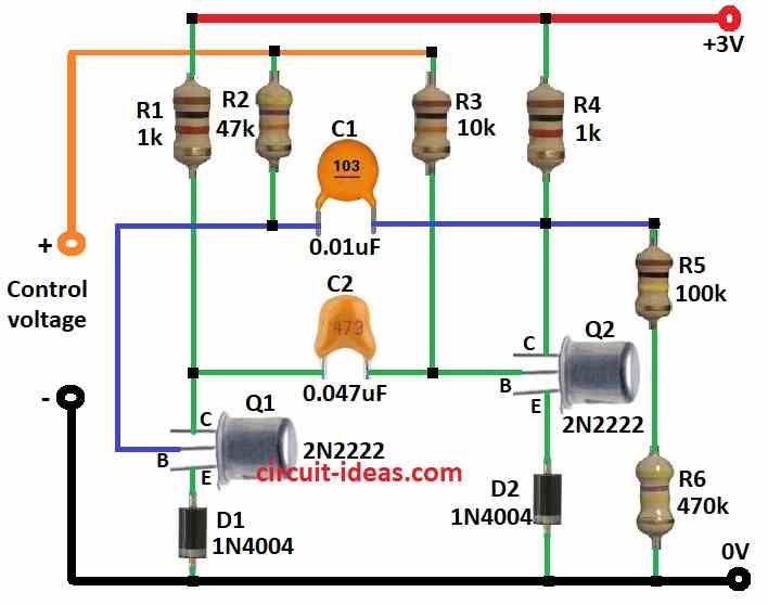
Parts List:
| Category | Item | Quantity |
|---|---|---|
| Resistors (All resistors are 1/4 watt unless specified) | 1k | 2 |
| 47k | 1 | |
| 10k | 1 | |
| 100k | 1 | |
| 470k | 1 | |
| Capacitors | Ceramic 0.01µF | 1 |
| Ceramic 0.047µF | 1 | |
| Semiconductors | Transistors 2N2222 | 2 |
| Diodes 1N4004 | 2 |
This circuit is well known as astable multivibrator.
It makes square wave and how fast it make wave depends on voltage at V1.
If voltage is high then frequency becomes high and if voltage is low then frequency also goes low.
Many other oscillator circuits also change with voltage.
VCO circuits have many uses.
They can make sound to show if voltage in circuit or power source is changing.
They also give warning if voltage is too much.
People also use them in music instruments and other electronic devices.
Formulas:
Main difference between astable multivibrator and VCO is that VCO use control voltage to change how fast it oscillate and even if both work on same basic idea.
Simple Formula for Astable Multivibrator:
The frequency (f) for normal astable multivibrator with two same RC parts is:
f = 1 / (1.4 × R × C)
where:
- f is frequency in hertz
- R is resistance in ohms
- C is capacitance in farads
General VCO Formula:
VCO formula can change based on how circuit is made but normally it looks like:
f = K × (Vcontrol – Voffset)
where:
- f is the frequency
- K is constant decided by circuit parts
- Vcontrol is the control voltage
- Voffset is small voltage to set starting frequency
Note:
For very accurate VCO work people often use special VCO ICs or better oscillator circuits.
How to Build:
To build a Simple Voltage Controlled Oscillator Circuit follow the below mentioned steps:
Construction Steps:
- Connect R1 and R2 one after another in series between power supply Vcc.
- Put capacitor C1 between point where R2 and R3 meet.
- Connect transistors Q1 and Q2 in cross way with their emitters going to ground through diodes D1 and D2.
- Connect collectors of both Q1 and Q2 to Vcc.
- Connect base of Q1 using capacitor C1.
- Connect base of Q2 using capacitor C2.
Adjustment and Testing:
- Use oscilloscope to check output frequency at collector of Q1 or Q2.
- Ensure circuit is working in correct frequency range and it reacts when control voltage is changed.
Notes:
- This VCO circuit we can improve it for special needs.
- Which parts we use like resistor, capacitor, etc. will decide frequency range and how stable the circuit is.
- Be careful when choosing parts and making the layout it will affects how good the circuit will work.
Conclusion:
Simple Voltage Controlled Oscillator Circuit is a circuit that gives output signal where frequency changes based on input voltage.
It is used in many places like communication systems, testing devices and music instruments where correct frequency is important.
References:
The Basics of Voltage Controlled Oscillators (VCOs) and How to Select and Use Them