Simple Wall Adapter to Battery Changeover Circuit is very useful for battery systems, as it help to switch power between wall adapter which is main and battery which is backup without stop power.
So device get power all the time with no break.
Furthermore, LTC4412 IC is very important part of this circuit and it control P-channel MOSFET like perfect diode and this make power switch smooth and efficient.
Emergency lights, portable devices and UPS systems also use this circuit.
Therefore, this article explains how the circuit works, how to design it, and how to build it easily using the LTC4412.
Circuit Working:
Parts List:
| Components | Values | Quantity |
|---|---|---|
| Capacitor | Electrolytic 22μF 25V | 1 |
| Semiconductors | IC LTC4412 | 1 |
| P-channel MOSFET FDN306P | 1 | |
| Schottky Diode 1N5819 | 1 |
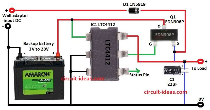
Circuit diagram show main parts of system and main part is LTC4412 IC with P-channel MOSFET FDN306P, Schottky diode 1N5819 and backup battery.
When wall adapter give power the LTC4412 IC1 use that first and then Schottky diode D1 stop power going back to adapter.
Then MOSFET Q1 turns ON and send power from adapter to load and battery stays OFF to save charge.
IC1 quickly switches to the battery when we remove the adapter or when it stops working, which keeps the power supply running.
The status pin of the IC indicates which power source is active.
After that, capacitor C1 help keep voltage stable when switch happen.
Note: Adapter input is 3V to 28V DC and battery can be 2.5V to 28V.
Formulas with Calculations:
How to Design Wall Adapter to Battery Changeover Circuit:
1. Drain to Source Voltage V_DS:
MOSFET V_DS must be more than input voltage with formula.
V_DS > V_input
Example: input is 12V so V_DS > 12V
2. On-Resistance R_DS(on):
MOSFET must have low R_DS(on) to reduce power loss.
Power loss: P_loss = I_load² × R_DS(on)
3. Drain Current I_D:
MOSFET I_D must be more than load current.
I_D > I_load
where:
- V_DS is the drain source voltage rating
- R_DS(on) is on-resistance which should be low.
- I_D is the drain current which must be higher than load
4. Capacitance C1:
Capacitor smooths the voltage during switching.
Formula: C = (I_load × Δt) / ΔV
where,
- I_load is the load current A
- Δt is the switching time s
- ΔV is the allowed ripple V
Example:
If I_load = 1A, Δt = 1ms and ΔV = 0.1V
C = (1 × 0.001) / 0.1 = 0.01F = 10,000µF
Note: In this circuit 22µF is OK because load is small and LTC4412 IC switch is fast.
How to Build:
To build a Simple Wall Adapter to Battery Changeover Circuit follow the below mentioned steps for connections:
- First, get all parts from circuit diagram.
- Next, connect pin 1 of IC1 to drain of MOSFET Q1.
- Then connect pin 2 and pin 3 of IC1 to GND.
- After that, connect pin 5 of IC1 to gate of MOSFET Q1.
- Now connect pin 6 of IC1 to source of MOSFET Q1, then from source of Q1 connect to positive of load and load negative goes to GND.
- Also, connect positive of capacitor C1 to source of Q1.
- Further, connect cathode of diode D1 to same source point which is the positive of C1 and anode of D1 goes to positive of wall adapter.
- Finally, wall adapter negative goes to GND.
Conclusion:
To conclude, this Simple Wall Adapter to Battery Changeover Circuit change power smooth from wall adapter to battery with no break.
Also, LTC4412 IC make design easy, work good and is quite reliable, hence, this circuit is best for low power devices which need good backup system.
Leave a Reply