• Skip to primary navigation
  • Skip to main content
  • Skip to primary sidebar

Circuit Ideas for You

Get free circuit ideas online.

  • Home
  • Privacy Policy
  • About
Home » Water Level Controller Circuit using IC 555

Water Level Controller Circuit using IC 555

Last updated on 13 August 2025 by Admin-Lavi Leave a Comment

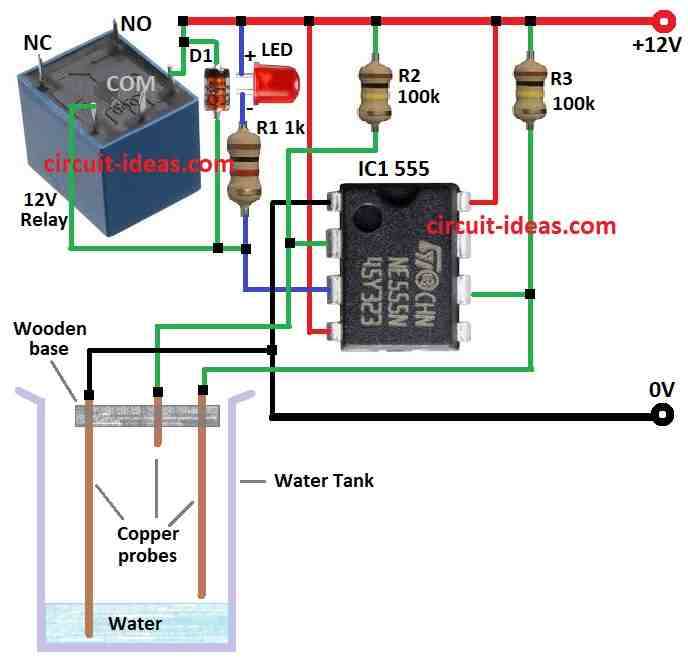
We can make simple Water Level Controller Circuit using IC 555 for our tank.

It stop pump when tank is full and start again when water is low.

We can change some parts to match our tank size and water level.

Circuit Working:

Water Level Controller Circuit Diagram using IC 555

Parts List:

CategoryDescriptionQuantity
Resistors1k 1/4 watt1
100k 1/4 watt2
SemiconductorsIC 5551
LEDs any 5mm 20mA1
Diode 1N4148 (D1)1
12V Relay1
Water Tank1
Copper probes3

This circuit is cheap because it uses easy parts.

Because of 100k resistors, pins 2 and 6 show voltage even when water does not touch the probes.

When water touches the probes then there is no voltage at these pins.

Pins 2 and 6 just check 1/3 and 2/3 of power.

They only see voltage or no voltage.

Pin 2 is LOW then pin 6 goes HIGH means normal.

Pin 2 is HIGH means nothing happens.

Pin 6 is LOW means nothing happen.

Water LOW means pins 2 and 6 HIGH and output pin 3 is LOW.

Water goes up and output remains same then chip wait until pin 2 goes LOW.

When water reaches pin 2 and pin 2 is not HIGH then output goes HIGH and pump stops.

Water drop and pin 2 is HIGH then nothing happens.

Water drop more then pin 2 is not LOW and pin 6 HIGH and output goes LOW and pump start.

Safety Tips:

  • Be careful when working with electricity.
  • Use correct parts and right voltage rating.
  • Know basic electronics before doing this.

Conclusion:

We can use 555 IC to make DIY Water Level Controller Circuit.

It fills tank and stops overflow using pump, probes and timer output.

This circuit is cheap and useful but safety and correct setup is important.

References:

WATER LEVEL CONTROLLER USING 555 TIMER IC

Filed Under: Water Level Controller

About Admin-Lavi

Lavi is a B.Tech electronics engineer with a passion for designing new electronic circuits. Do you have questions regarding the circuit diagrams presented on this blog? Feel free to comment and solve your queries with quick replies

Previous Post: « Header Tank Water Level Controller Circuit
Next Post: IC 555 Solar Charger Controller Circuit »

Reader Interactions

Leave a Reply Cancel reply

Your email address will not be published. Required fields are marked *

Primary Sidebar


Categories

  • Alarm Circuits (34)
  • Amplifier Circuits (67)
  • Arduino Projects (58)
  • Audio Circuits (98)
  • Automobile Circuits (19)
  • Battery Charger Circuits (49)
  • Free Energy (13)
  • Heater and Temperature Controllers (10)
  • High Voltage (1)
  • Indicator Circuits (40)
  • Inverter Circuits (14)
  • LDR Circuits (17)
  • LED and Lamps (117)
  • Meters and Testers (28)
  • Motor Controllers (18)
  • Oscillator Circuits (34)
  • Power Supply Circuits (92)
  • Remote Control Circuits (7)
  • Security and Protection (26)
  • Sensors and Detectors (97)
  • Solar Circuits (17)
  • Timer Circuits (30)
  • Transistor Circuits (57)
  • Transmitter Circuit (14)
  • Tutorials (5)
  • Water Level Controller (4)

Recent Posts

  • Audio Spectrum Analyzer Circuit using IC MSGEQ7
  • RGB LED Color Control Circuit with LDR and Arduino
  • Arduino Based GPS Digital Clock Circuit
  • Small UPS Circuit for Router Backup
  • Sound Activated LED Circuit with Arduino

Recent Comments

  1. Admin-Lavi on Constant Voltage, Constant Current Battery Charger Circuit
  2. Bill on Constant Voltage, Constant Current Battery Charger Circuit
  3. Admin-Lavi on Long Range FM Transmitter Circuit (2km)
  4. Sina on Long Range FM Transmitter Circuit (2km)
  5. Admin-Lavi on Long Range FM Transmitter Circuit (2km)

Copyright © 2025 | New Circuit Ideas