This Simple Water Level Indicator Circuit using IC ULN2004 work like small helpers for our water tank.
It uses one special chip named as ULN2004 to control many things together.
This chip can work with big electricity but here it only control lights.
The lights show how much water is inside the tank.
So with this circuit we can see easily if tank need more water or if water is too much.
Circuit Working:
Parts List:
| Category | Component | Quantity |
|---|---|---|
| Resistors | 180Ω 1/4 watt | 7 |
| Semiconductors | IC ULN2004 | 1 |
| LEDs Red 5mm 20mA | 7 | |
| Green 5mm 20mA | 7 | |
| Water Tank | 1 | |
| Probes (brass or chromium plated) | 8 |
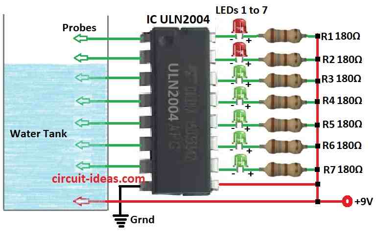
This water level indicator shows how much water is in overhead tank.
Circuit is simple and uses one IC ULN2004 and small parts.
Each IC input connects to metal probe to check water.
Output connects to LEDs with resistors.
One common probe connects to positive wire.
When water touches the probe then LED lights ON.
Make circuit on normal PCB put in small box.
Use brass or chrome pins for probes and connect with 3 core shielded wire.
Fix probes in tank with low, middle, high.
When no water then there is no light.
When water rises then green lights turn ON one by one.
And when tank is full then red light gets ON.
So when all green and red LEDs are ON means tank is full.
Formula:
From this circuit diagram we can use formula for Power Dissipation and Heatsink for IC ULN2004:
Power Dissipation and Heatsink:
ULN2004 have maximum power limit.
If we use big current on output then maybe it may need heatsink and so it is better to check power use.
Use this formula:
Pd = Vout × Iout
where:
- Vout is the voltage at output in volts
- Iout is the current at output in amps
How to Build:
To build a Simple Water Level Indicator circuit using IC ULN2004 we need to follow the below mentioned connection steps:
- Design or get one PCB layout that fit ULN2004 IC, resistors, LEDs and wire for probes.
- Put all parts on PCB like in above circuit diagram.
- Solder ULN2004 IC on PCB and be sure to put it correct way.
- Solder resistors to LED anode side and then connect LED cathode to output pin of ULN2004.
- Connect 7 probes to input pins of ULN2004 IC.
- One probe is common probe and connect this one to positive wire.
- Place PCB inside small box and fix it so it may not move.
- Make small holes in box for probe wires to come out.
- Close and seal box so no water go inside.
- Put probes from side of a tank.
- Low probe go bottom, middle probe in center, and high probe on top.
- Use 3 core shield wire to connect probes to PCB.
- Turn ON power and fill tank with water.
- Check if LEDs turn ON step by step as water goes up.
- Be careful and always follow safety rules when working with electric and water.
Conclusion:
To conclude this Simple Water Level Indicator Circuit using IC ULN2004 is easy and good way to check water level in overhead tank.
It uses Darlington transistor array inside the IC and some small parts to show water level using LEDs.
This project is not too hard to make and can help in water saving and control system.