This Simplest Blown Fuse Indicator Circuit shows if fuse is good or bad without checking it by hand; also if fuse is okay then green LED turns ON.
Furthermore, if fuse blows then green LED goes OFF and red LED turns ON and that means fuse is bad and needs to change.
Circuit Working:
Parts List:
| Components | Values | Quantity |
|---|---|---|
| Resistor | 1k 1/4 watt | 1 |
| Semiconductors | Diode 1N4148 | 1 |
| LED Red 5mm, 20mA | 1 | |
| LED Green 5mm,20mA | 1 | |
| Fuse | 1 |
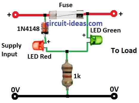
This circuit uses two LEDs, one red and one green, along with a diode to indicate whether the fuse has blown.
How it works:
When fuse is good then current flows normally and very small voltage drop across the fuse.
Most voltage goes through diode 1N4148 around 0.7V and then red LED stays OFF because not enough voltage turn it ON; and finally, green LED gets full voltage and lights up.
If fuse blows:
Circuit opens with no current flow and voltage now drops across the blown fuse.
Red LED gets enough voltage and turns ON and shows fuse is bad and green LED gets no power and turns OFF.
Formulas:
From the circuit with LED green and red lights up depends on voltage drop across the resistor and LED.
Choosing Resistor:
We need to pick right resistor for green LED and this depends on:
Supply voltage Vsupply
LED forward voltage VfLED
Desired current ILED
Use ohms law:
R = (Vsupply – VfLED) / ILED
where:
- VfLED is the forward voltage of green LED
- R is the resistor in ohms Ω
- Vsupply is the supply voltage in volts V
- ILED is the current through LED in amps A
Tips:
Check green LED datasheet for VfLED and choose ILED within safe range usually from 10 to 20 mA
Try different resistor values or use online LED calculator and also check the LED lights are bright enough, but not with too much current.
How to Build:
To build a Simplest Blown Fuse Indicator Circuit we need to follow the below mentioned connections steps:
- First, find positive and negative rows on PCB and then connect power supply (+) to positive row and also connect power supply (–) to negative row.
Place LEDs and Resistor:
- Next, put red and green LEDs on PCB and legs in different rows and short legs cathodes of both LEDs should be on same side.
Connect Green LED:
- After that, solder long leg anode of green LED to same row as (+) supply.
Resistor Setup:
- Now put 1k resistor near the short legs cathodes of LEDs, with one leg of resistor goes with LED cathodes and other leg of resistor goes to supply row.
Red LED Cathode:
- Short leg of red LED connects to resistor side.
Place Diode 1N4148:
- Then put diode on PCB with band side cathode facing (+) supply and band side goes to (+) supply row.
Connect Red LED Anode:
- Also, long leg anode of red LED connects to diodes non band side.
Find two ends of the fuse.
- One end of fuse goes to (+) supply row and other end goes to load side.
Testing ensure power is OFF first:
- Turn the power ON, if the fuse is good, the green LED lights up; but however, if the fuse has blown then the red LED lights up.
Safety Tips:
- Double check all connections before powering ON and use 2 to 3V power for small LEDs.
- Do not touch live circuit.
- Ask expert if anyone is unsure about this project.
Conclusion:
To conclude, this Simplest Blown Fuse Indicator Circuit shows the fuse status: the green LED indicates that the fuse is intact, while the red LED indicates that the fuse has blown.
Also, this simple circuit shows fuse status using lights and it helps in checking and fixing problems in electronics.