Basic H-bridge PWM circuit uses IC 555 which helps to control dog barking and stop it.
Main part is ultrasonic tweeter.
It work with two IC 555 and four driver transistors.
Circuit Working:
Parts List:
| Category | Description | Quantity |
|---|---|---|
| Resistor | 1k 1/4 watt | 1 |
| Potentiometer 100k | 1 | |
| Capacitor | Ceramic 1nF | 1 |
| Semiconductors | IC 555 | 2 |
| Transistors BD679 | 2 | |
| Transistors BD680 | 2 | |
| Ultrasonic Tweeter | 1 |
Two 555 IC are used in this circuit which are IC1 and IC2 in the circuit diagram and are very important.
IC1 work as astable multivibrator and it make PWM signal at pin 3.
PWM signal change by resistor pot R1 and capacitor C1 and they control frequency and duty cycle.
IC2 work like flip-flop (set/reset) and it controls signal based on IC1 output.
When pin 3 of IC1 is high then pins 2 and pin 6 of IC2 goes above 2/3 VCC.
Then pin 3 of IC2 goes low and tweeter push outward.
When pin 3 of IC1 is low then pins 2 and 6 of IC2 go below 1/3 VCC.
Then pin 3 of IC2 goes high and tweeter pull inward.
Changing potentiometer changes resistance and this changes duty cycle and timing of C1 charge/discharge.
Ultrasonic tweeter is load and it move push-pull by four transistors T1 to T4 in H-bridge.
H-bridge let tweeter move both ways and it turn ON/OFF by PWM from IC1.
IC1 give PWM signal and its duty cycle is set frequency of tweeter.
To change duty cycle we need to adjust potentiometer.
Circuit need 12V power to work.
Formulas
Using IC 555 as astable multivibrator we need to make sound that dogs do not like.
It help stop their barking.
Here is formula:
Frequency (f):
f = 1.44 / (R1 + 2R2) * C
where,
- R1 and R2 are resistors and it is connected to IC 555.
- C is timing capacitor.
Change R1, R2 and C to get right frequency.
For ultrasonic sound we need to ensure it is safe for humans and dogs.
How to Build:
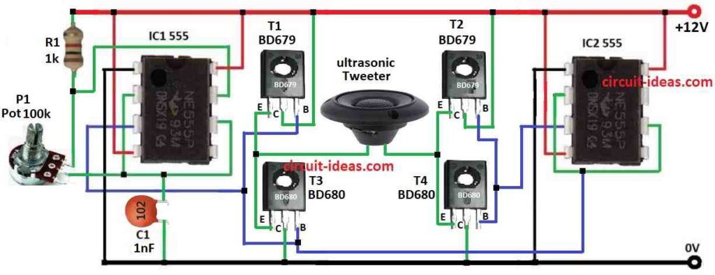
To build a Stop Dog Barking using IC 555 Circuit follow the below mentioned steps for connections:
- Gather all parts as shown in circuit diagram.
- Pin 1 of IC1 goes to ground.
- Pin 2 connect to pin 6 of IC1.
- Pin 3 of IC1 goes to base of transistors T1 and T3.
- Pin 4 of IC1 goes to +12V.
- Pin 6 connect back to pin 2 of IC1.
- Pin 7 goes between resistor R1 and one leg of pot.
- Pin 8 of IC1 goes to +12V.
- Capacitor C1 connect from pin 2/6 to ground.
- Middle leg of pot P1 goes to pin 2/6 of IC1.
- Pin 1 of IC2 goes to ground.
- Pins 2 and 6 of IC2 connect to pin 3 of IC1.
- Pin 3 of IC2 goes to base of T2 and T4.
- Pin 4 of IC2 goes to +12V.
- Pin 6 connect back to pin 2 of IC2.
- Pin 8 of IC2 goes to +12V.
- Tweeter connect between emitters of T1/T3 and T2/T4.
- Emitter of T1 connect to emitter of T3.
- Collector of T1 goes to +12V.
- Collector of T3 goes to ground.
- Base of T1 connect to base of T3.
- Emitter of T2 connect to emitter of T4.
- Collector of T2 goes to +12V.
- Collector of T4 goes to ground.
- Base of T2 connect to base of T4.
Conclusion:
This Stop Dog Barking using IC 555 Circuit is to make high frequency square wave.
This wave control H-bridge circuit that switch voltage fast on tweeter.
Fast switching make ultrasonic sound that dogs do not like but which humans cannot hear.