Water may look clean, but it can contain hidden dirt that we cannot see; also tiny particles such as dust, clay, and silt make the water cloudy and we call this cloudiness turbidity.
More turbidity means more dirt and bad water and less turbidity means clean and safe water; therefore, this project uses Arduino and turbidity sensor to check water.
In addition, it shows result on LCD and color lights and also this article shows working, coding and how to build it.
Arduino Code:
#include <Wire.h>
#include <LiquidCrystal_I2C.h>
LiquidCrystal_I2C lcd(0x27,16,2);

int sensorPin = A0;
int red = 2;
int green = 3;
int blue = 4;

void setup() {
lcd.init();
lcd.backlight();
pinMode(red, OUTPUT);
pinMode(green, OUTPUT);
pinMode(blue, OUTPUT);
}

void loop() {
int value = analogRead(sensorPin);
float voltage = (value / 1023.0) * 5.0;
lcd.setCursor(0,0);
lcd.print("Turbidity:");
lcd.setCursor(0,1);
lcd.print(voltage);
lcd.print(" V");

if(voltage > 4.0){
digitalWrite(red, HIGH);
digitalWrite(green, LOW);
digitalWrite(blue, LOW);
}
else if(voltage > 2.5){
digitalWrite(red, LOW);
digitalWrite(green, LOW);
digitalWrite(blue, HIGH);
}
else{
digitalWrite(red, LOW);
digitalWrite(green, HIGH);
digitalWrite(blue, LOW);
}
delay(1000);
}
Coding Explanation:
- Add LCD library.
- Set sensor pin as A0.
- Set RGB LED pins as D2, D3, D4.
- In setups start LCD.
- Turn ON LCD backlight.
- Set RGB pins as output.
- In loop read sensor value from A0.
- Change value to voltage.
- Show voltage on LCD.
- If voltage > 4.0 then red LED will be ON.
- Else if voltage > 2.5 then blue LED will be ON.
- Else green LED will be ON.
- Wait 1 second.
- Loop runs again.
- Arduino keeps checking water.
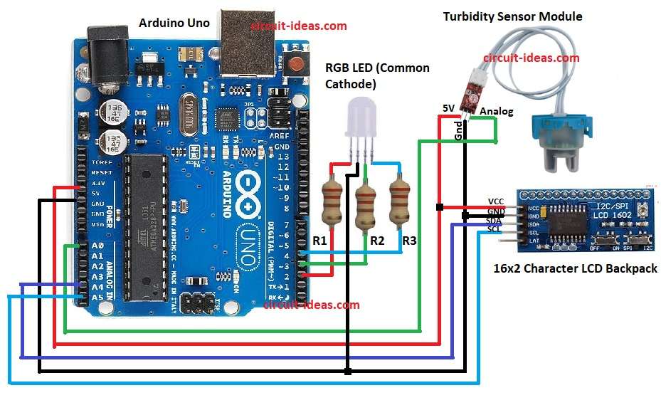
Circuit Working:
Parts List:
| Components | Quantity |
|---|---|
| Resistor | |
| 220Ω 1/4 watt | 3 |
| Semiconductors | |
| Arduino Uno | 1 |
| Turbidity Sensor Module | 1 |
| SPI/I2C Serial 16×2 Character LCD Backpack | 1 |
| RGB LED (Common Cathode) | 1 |
Turbidity sensor has IR LED and photodiode inside and clear water lets more light pass and dirty water blocks light.
Then sensor gives analog output voltage and Arduino reads this from A0 and then Arduino shows value on LCD through I2C.
After that, the RGB LED provides a quick visual indication.
Resistors R1 to R3 limit the current flowing through the LED pins, and the Arduino connects both the LCD and the RGB LED to its digital pins.
Now put sensor in water, then Arduino reads analog value and when water is clean then voltage is low and when water is dirty then voltage goes high.
Further, Arduino checks voltage and changes LED color and then LCD shows the voltage; hence, through this user can know water quality.
Formulas:
Below is the general formula for Water Quality Test Circuit using Arduino and Turbidity Sensor:
Voltage = (AnalogValue / 1023) * 5
Example: if AnalogValue = 820 then
Voltage = (820/1023)*5 = 4.00V
Higher voltage means more turbidity and lower voltage means less turbidity
How to Build:
To build a Water Quality Test Circuit using Arduino and Turbidity Sensor follow the below steps for connections:
- First, gather all parts as shown in circuit diagram.
- Next, turbidity sensor 5V go to Arduino 5V, turbidity sensor GND go to Arduino GND and turbidity sensor analog pin go to Arduino A0.
- Now connect LCD VCC to Arduino 5V, connect LCD GND to Arduino GND, connect LCD SDA to Arduino A4 and connect LCD SCL to Arduino A5.
- After that, connect RGB LED common cathode to Arduino GND, connect RGB LED Red pin to Arduino D2, connect RGB LED Green pin to Arduino D3 and then connect RGB LED Blue pin to Arduino D4.
- Also cathode pin 2 of RGB LED connect to GND and finally, add resistors R1 to R3 220Ω in series with each LED pin (R, G, B)
Conclusion:
Overall, this project for Water Quality Test Circuit using Arduino and Turbidity Sensor is easy and with low cost, it checks water quality using turbidity sensor.
Arduino shows result on LCD and color lights and it helps to know clean or dirty water; also this project is useful for home, school and lab use.