In our previous post for ±15V Dual Power Supply Circuit using 7815 and 7915 ICs, now in this post we will generate +15V and −15V using a two terminal AC transformer.
The circuit uses rectifier diodes, filter capacitors and voltage regulator ICs, the regulators used are same 7815 for positive voltage and 7915 for negative voltage.
These regulators give stable output voltage and output current can reach about 1A.
Therefore, this ±15V Dual Regulator Circuit using Two Terminal Transformer is useful for lab power supply, amplifier circuits and op-amp applications.
Circuit Working:
Parts List:
| Components | Specifications | Quantity |
|---|---|---|
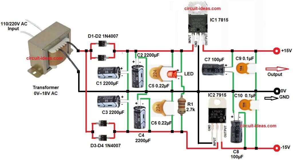
| Resistor | 2.7k 1/4 watt | 1 |
| Capacitors | Electrolytic 2200µF 35V | 4 |
| Electrolytic 100µF 35V | 2 | |
| Ceramic 0.22µF 50V, 0.1µF | 2 each | |
| Voltage Regulator IC 7815, 7915 | 1 each | |
| Standard Indicator LED 5mm | 1 | |
| Rectifier Diode 1N4007 | 4 | |
| 18V AC Step-Down Transformer with Two-Terminal primary 110/220V AC, secondary 0–18V AC | 1 |
First, AC mains power enters the transformer and the transformer reduces the voltage to about 18V AC.
Next, the AC voltage enters the diode rectifier section, diodes D1 and D2 make the positive rectification path and diodes D3 and D4 make the negative rectification path.
So the circuit creates both positive DC and negative DC voltage but the rectified voltage still has ripple.
So capacitors C1, C2, C3 and C4 filter the voltage and these capacitors store electric charge, as they reduce the ripple and make smoother DC voltage.
After this filtering stage the DC voltage enters the voltage regulators.
IC1 is the 7815 regulator and this IC gives regulated +15V output.
IC2 is the 7915 regulator and this IC gives regulated −15V output.
Small capacitors C5 and C6 help the regulators work stable.
Capacitors C7, C8, C9 and C10 remove high frequency noise from the output.
LED1 and resistor R1 work as power indicator and when the circuit runs the LED turns ON.
Finally the circuit gives three output terminals: +15V, GND, −15V
How to Build:
To build a ±15V Dual Regulator Circuit using Two Terminal Transformer follow the below connection steps:
- Start, gathering all the circuit parts as shown in circuit diagram above.
- Then start with transformer secondary with first wire connect to diodes D1-D2 and and same wire to diode D3-D4.
- Second transformer secondary wire goes to 0V gnd.
- Diodes D1 and D2 cathode ends go to high filter capacitors C1 -C2 positive end and negative end goes to GND.
- Diodes D3 and D4 anode ends go to high filter capacitors C3 -C4 negative end and positive end goes to GND.
- After that connect capacitor C5 and C6 in series from input pin of IC1 7815 and GND, and from GND to input pin of IC2.
- After this connect LED and resistor R1 in series from input pin of IC1 and to input pin of IC2.
- Then start with positive regulator IC 7815 pin input connect to positive filtered DC voltage
Ground pin connect to common ground 0V. - Output pin goes to regulated +15V output.
- And after that start with 7915 negative regulator ground connect to common ground 0V.
- Input pin connect to negative filtered DC voltage.
- Output pin connects to regulated −15V output.
- Then connect the output side capacitor C7 and C8 connect at regulator outputs for filtering.
- And finally, connect C9 and C10 at regulator outputs which remove high frequency noise.
Conclusion:
This ±15V Dual Regulator Circuit using Two Terminal Transformer is a simple dual power supply which produces +15V and −15V regulated outputs.
The design uses common components like 7815 and 7915 regulators ICs which also uses standard rectifier diodes and filter capacitors.
Therefore, the circuit is easy to build and reliable, as this power supply is suitable for operational amplifier circuits, audio amplifiers, analog electronics and laboratory projects.
With proper heat sink on regulators the circuit can supply up to 1A current safely.
Leave a Reply