This article explain us about a simple 24V 2A Zener Transistor Voltage Regulator Circuit, which converts 230V AC into stable 24V DC output.
Moreover, this circuit uses step down transformer, rectifier diodes, filter capacitors, Zener reference and power transistor.
Also, this circuit gives good voltage stability even when load changes, because of this output voltage stays near constant value.
Next, this type of regulator is called linear regulator, which is simple but not very efficient, as some power is lost as heat, so heat sink is important for transistor to avoid damage.
We can use this power supply circuit for small DC motors, audio projects and for general electronics testing.
Circuit Working:
Parts List:
| Components | Values | Quantity |
|---|---|---|
| Resistors | 1k, 2.2k 1/4 watts | 1 each |
| Capacitors | Electrolytic 4700µF 63V | 1 |
| Electrolytic 220µF 50V | 2 | |
| Ceramic 0.1µF | 1 | |
| Transistor TIP142 | 1 | |
| Heatsink for TIP142 | 1 | |
| Any standard LED | 1 | |
| Zener Diodes 12V, 13V | 1 each | |
| Diodes 1N5407 | 4 | |
| On Off switch | 1 | |
| Fuse 1A | 1 | |
| Transformer primary 230V AC, secondary 0V-24V 3A | 1 |
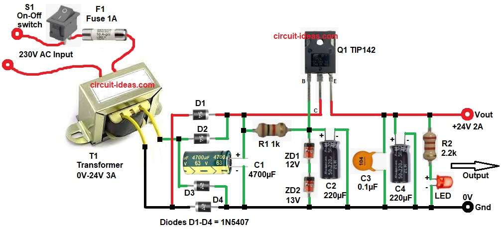
Circuit starts, with AC 230V goes into transformer T1 through F1 fuse and S1 switch and transformer reduces voltage to 24V AC.
Next, diodes D1, D2, D3, D4 make bridge rectifier and they convert AC to pulsating DC.
After that, capacitor C1 smooths the DC and removes ripple, but now the circuit gives unregulated DC around 30V to 34V.
Then the regulator stage works, with resistor R1 supplies current to Zener diodes ZD1 and ZD2 and these Zener diodes create fixed reference voltage around 25V (12V + 13V).
Transistor Q1 TIP142 works as series pass element, with base of transistor connects to Zener reference, emitter of transistor gives output voltage and output becomes stable near at 24V.
Capacitors C2, C3, C4 help in filtering noise and improve stability and LED with resistor R2 shows power ON indication.
Note: Circuit can give 24V output, but 2A current depends only on following:
- We must use 24V 2A or higher like 3A transformer.
- Large heat sink is needed for transistor TIP142.
- And only good cooling can reach upto 2A.
If the above points are not followed then, it will overheat and not give full 2A current.
How to Build:
To build a 24V 2A Zener Transistor Voltage Regulator Circuit follow the below connection steps:
- First, the circuit starts by assembling all the parts as in circuit diagram.
- Next connect transformer T1 with primary end to 230V AC input and secondary end goes to 24V AC output.
- After that, connect bridge rectifier diodes D1 to D4 in bridge form, with AC inputs connect to transformer secondary and positive and negative outputs go to filter.
- Now, connect capacitor C1 positive pin to rectifier positive and negative pin to ground.
- Then connect resistor R1 one side go to positive DC and other side to junction of Zener network, and base of transistor Q1.
- Next, connect Zener diodes ZD1 and ZD2 in series with cathode of ZD1 is connected to to R1 and base of Q1 and anode of ZD2 to ground.
- After that, connect transistor Q1 TIP142 with base pin to junction of R1 and Zener’s, collector pin connects to unregulated DC and emitter goes to regulated output of +24V.
- Then, connect capacitors C2, C3, C4 across output in parallel and ground for filtering.
- Finally, resistor R2 and LED are connected in series with cathode of led to gnd.
Conclusion:
To conclude, this 24V 2A Zener Transistor Voltage Regulator Circuit is simple and reliable and it uses basic components and easy design.
Zener diodes control voltage and transistor gives current boost.
Circuit gives stable output for many applications, with proper heatsink and good transformer selection improve performance.
This design is good for learning and practical use.
Leave a Reply