24V Battery Charger Circuit for Lead Acid Batteries with IC LM317 is a very useful useful project.
It helps battery work good and last long.
This charger is made special for 24V 7AH lead acid battery.
It uses IC LM317 to control voltage and also control current so battery charge is safe and correct.
Circuit Working:
Parts List:
| Component | Specification | Quantity |
|---|---|---|
| Resistors | 100Ω 1/4 watt | 1 |
| 0.85Ω 2W | 1 | |
| 220Ω 1/4 watt | 1 | |
| Preset 10k | 1 | |
| Semiconductors | IC LM317 | 1 |
| Transistor BC547 | 1 | |
| Capacitors | Electrolytic 2200μF 50V | 1 |
| Electrolytic 100μF 50V | 1 | |
| Diodes 1N5402 | 1 | |
| Bridge Rectifier 1N5402 | 4 | |
| Fuse 2A | 1 | |
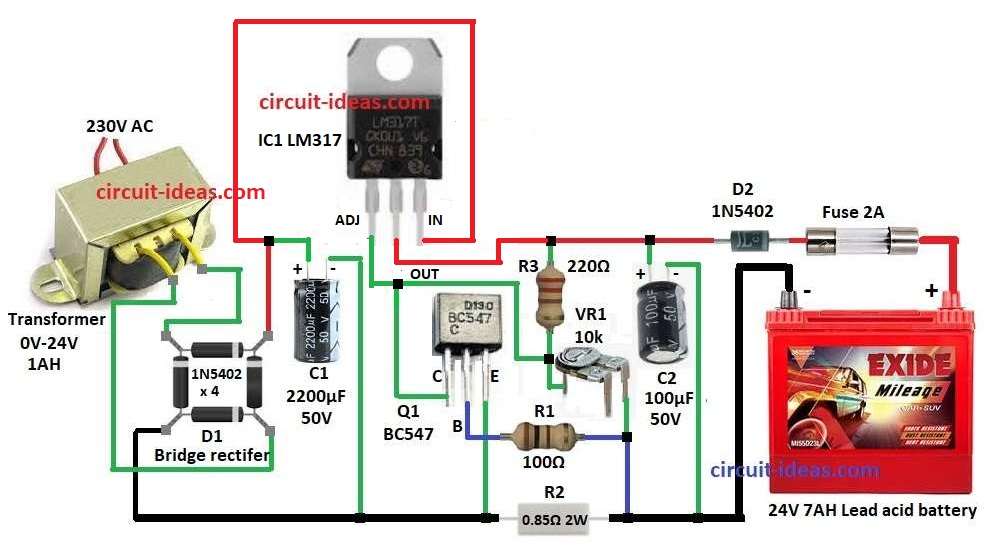
| Transformer 0V-24V 1AH, 230V primary, 35V/3A secondary step-down | 1 |
230V AC change to 35V AC using step-down transformer.
Then 35V AC change to DC using bridge rectifier D1.
Capacitor C1 2200µF is used to smooth DC and remove voltage bumps.
LM317 IC control voltage and gives right charging voltage.
Output voltage depend on resistors R3 and VR1 setting.
Transistor Q1 BC547 and resistor R2 limit charging current and protect from too much current.
Diode D2 stop reverse current from battery to circuit.
R2 is 0.85 ohm which is not common.
Make it using 6.2 ohm and 1 ohm in parallel.
Battery connect through fuse F1 and this fuse is used to protect from overcurrent or short circuit.
Formulas with Calculations:
1. Output Voltage Vout of LM317:
Formula:
Vout = Vref × (1 + VR1 / R3)
where,
- Vref is 1.25V for LM317 reference voltage
Example:
R3 = 220 ohms and VR1 = 10k ohms
Vout = 1.25 × (1 + 10000 / 220)
Vout = 24.1V
2. Current Limiting Resistor R2:
Formula:
R2 = 0.6 / Imax
Example:
Imax is 0.85A
R2 = 0.6 / 0.85 = 0.85 ohms
3. Capacitor Selection C1 & C2:
Formula:
C = I / (2 × f × ΔV)
where:
Example:
C1 is 2200µF used to work well in actual circuit.
These formulas help to set the output voltage, limit charging current and smooth the DC voltage.
How to Build:
To build a 24V Battery Charger Circuit for Lead Acid Batteries with IC LM317 following steps for connections are mentioned below:
- Place all parts as shown in circuit diagram.
- Connect input pin of LM317 IC1 to positive of C1 and negative of C1 to GND.
- ADJ pin of IC1 connect to collector of Q1 transistor.
- Output pin of IC1 connect to one end of R3 and other end of R3 go to middle leg of VR1 and 2nd leg of VR1 to GND.
- C2 positive side go to IC1 output and negative side go to GND.
- D2 diode anode go to IC1 output and cathode go to one side of fuse F1 and other side of fuse go to positive of battery.
- Negative of battery go to GND.
Bridge Rectifier D1:
- One pin goes to input of IC1
- Two pins go to wires from transformer
- Last pin to GND
Q1 Transistor:
- Collector pin to ADJ pin go of IC1
- Base pin go to GND through R1
- Emitter pin go to GND
- R2 0.85Ω resistor connects to GND which works as current limiter.
Conclusion:
This 24V Battery Charger Circuit for Lead Acid Batteries with IC LM317 is safe and good for charging small lead acid batteries.
It controls voltage and current and has reverse current protection and fuse for safety.
Follow the wiring and values, through this we can build this charger easily.
Leave a Reply