
This post is for simple 2N3055 Based 12V DC Voltage Regulator Circuit, which gives stable 12V output and is useful for power supply projects; for example, battery charger, amplifier supply, small lab supply and this circuit is easy to build.
The circuit uses low cost, readily available components and it operates as a series-pass transistor regulator, with a Zener diode controlling the transistors base voltage to maintain a stable output voltage.
Then transistor controls the output voltage and as a result, output stays near 12V even if input changes a little.
Circuit Working:
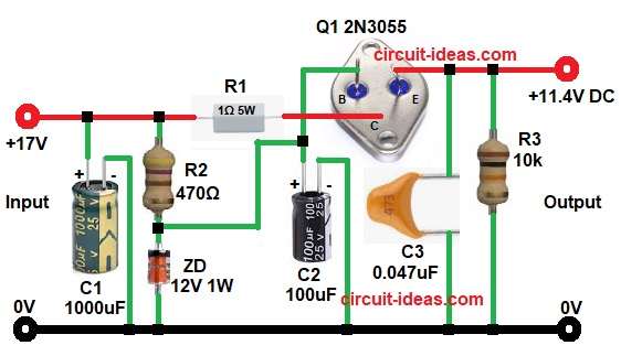
Parts List:
| Components | Values | Quantity |
|---|---|---|
| Resistors | 1Ω 5W, 470Ω 1/2W, 10k 1/4 W | 1 each |
| Capacitors | Electrolytic 1000uF 25V, 100uF 25V | 1 each |
| Ceramic 0.047uF 50V | 1 | |
| Semiconductors | Zener Diode 12V 1W | 1 |
| 2N3055 NPN Power Transistor | 1 |
First, the circuit receives an unregulated DC input, in the above circuit diagram, the input voltage is approximately 17V DC.
Capacitor C1 then filters the rectifier output by reducing ripple, producing a smoother DC input for the regulator.
Next, R2 supplies current to the 12V Zener diode, allowing it to maintain a constant 12V at its cathode.
The Zener diode then provides this regulated voltage to the base of the 2N3055 transistor, keeping the base voltage at approximately 12 V.
Now, transistor works as emitter follower and this emitter voltage is always about 0.7V less than base voltage, so output voltage becomes:
Vout = Vz – Vbe
If Zener is 12V and Vbe is 0.7V then:
Vout = 12 – 0.7
Vout = 11.3V
So output is approximately 11.4V as shown in diagram.
R1 1Ω acts as a current sensing resistor that slightly limits the current and protects the transistor and R3 10kΩ acts as a bleeder resistor that discharges the output capacitor when the power supply turned OFF.
C2 100µF improves the regulators stability and reduces noise and C3 0.047µF filters high frequency noise from the output.
Thus, output becomes stable DC around 12V.
Formulas with Calculation:
- Zener Resistor R2 Calculation:
R2 = (Vin – Vz) / Iz
where:
- Vin input DC voltage
- Vz is Zener voltage
- Iz is Zener current
Example:
Vin is 17V
Vz is 12V
Desired Iz = 10mA = 0.01A
R2 = (17 – 12) / 0.01
= 5 / 0.01
R2 = 500 Ohm
Nearest standard value of 470Ω resistor used in this circuit.
2. Power Dissipation of Transistor:
P = (Vin – Vout) x Iload
Example:
- Vin is 17V
- Vout is 11.4V
- Iload is 2A
P = (17 – 11.4) x 2
= 5.6 x 2
P = 11.2 Watt
Therefore, use a medium to large aluminum heat sink to dissipate heat effectively and we can also apply thermal grease to improve heat transfer.
How to Build:
To build a 2N3055 Based 12V DC Voltage Regulator Circuit follow the following connection steps:
- Start, the circuit by collecting all the circuit parts.
- Next, start with transistor Q1 collector pin connect to unregulated positive input of 17V through resistor R1, base connect to junction of R2 and Zener diode and emitter connect to output terminal of 11.4V.
- Then resistor R2 one end connect to input positive and other end connect to Zener cathode and transistor base.
- After that, Zener diode cathode connect to base of transistor Q1 and anode connect to ground 0V.
- Further, capacitor C1 positive end connect to to input positive and negative to ground.
- Now capacitor C2 positive connect to junction of transistor Q1 base, resistor R2 and Zener diode and negative to ground.
- Also, capacitor C3 one side to output and other side to ground and R3 connect between output and ground.
Important Notes
- Always use proper heat sink for 2N3055.
- Input voltage must be at least 2V to 3V higher than output.
- This is linear regulator and its efficiency is low at high current, for for higher efficiency, switching regulator is better.
Conclusion:
Overall, this 2N3055 Based 12V DC Voltage Regulator Circuit is simple and reliable project, as it gives stable output for medium current applications and its components are common and cheap.
However, heat dissipation is high so good heat sink is necessary and finally, it is good learning project and useful power supply for hobby electronics.