The LA4550 is a dual power amplifier IC that boosts low-level audio signals in audio systems; this circuit also powers small speakers, radios, and other audio devices.
It is easy to use and is highly efficient.
4W Audio Amplifier Circuit using IC LA4550 gives max 4W power and is good for small audio project and also it has cool features like:
- It uses very low power when idle.
- It has two channel: stereo or bridge mode.
- It reduces noise from power change and keeps left/right sound clear.
- There is no click noise on power ON/OFF
Circuit Working:
Parts List:
| Components | Values | Quantity |
|---|---|---|
| Resistors | 1Ω 1/4 watt | 3 |
| Capacitors | Ceramic 0.1µF | 4 |
| Electrolytic 100µF 25V | 5 | |
| Electrolytic 470µF 25V | 3 | |
| Semiconductor | IC LA4550 | 1 |
| Speaker 8Ω | 1 |
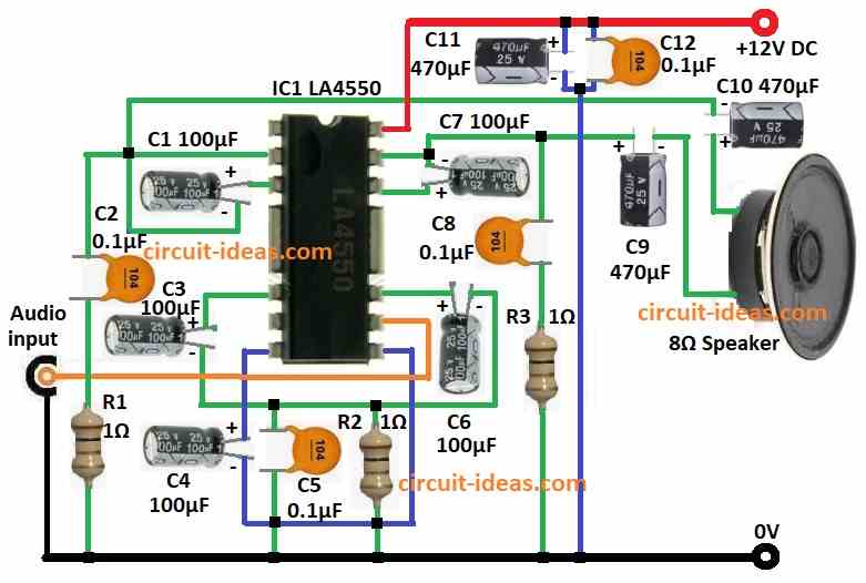
This is one channel audio amp using LA4550 IC and it work on 12V DC and powers 8 ohm speaker with 4W sound.
Audio goes in pin 4 through capacitor C4 and this C4 block DC and only lets audio pass, and then IC boost weak audio inside.
After that C2 and R1 help with feedback and keep circuit stable.
The IC design sets the gain and feedback components adjust it, then C1, C3 and C11 clean the power supply and reduce noise.
Boosted audio go to speaker through C9 and then C9 block DC and send only audio to speaker.
Hence, speaker change audio signal to sound.
Formulas with Calculations:
Formulas with example for 4W Audio Amp using LA4550:
Output Power:
P = V² / R
where,
- P is the power in watt
- V is the peak voltage from power supply
- R is the speaker resistance
Example:
12V supply with 8 ohm speaker:
P = 12² / 8 = 144 / 8 = 4W
Capacitor Select:
fc = 1 / (2πRC)
where,
- fc is the cutoff frequency
- R is the 8 ohm speaker
- C is the capacitor value
Example:
fc = 20Hz:
C = 1 / (2π × 8 × 20) = 0.99 µF
Power Loss (Dissipation):
PDISS = VCC × IQ
where,
- VCC is the supply voltage
- IQ is the idle current from IC datasheet
How to Build:
To build a 4W Audio Amplifier Circuit using IC LA4550 following are the connections steps to follow:
- First, get all parts from circuit diagram.
- Next, pin 2 of LA4550 connects one end of 8Ω speaker through cap C10.
- After that, pin 2 connects pin 3 through capacitor C3.
- Now pin 4 connects pin 9 through capacitors C3 and C6 also from pin 4 connects capacitor C5 and resistor R2 to GND.
- Then pin 6 connects pin 7 through capacitor C4.
- Also, pin 8 connects audio input.
- Further, pin 10 connects pin 11 through capacitor C10 and then pin 11 connects other end of 8Ω speaker through capacitor C9 and also from pin 11 connect capacitor C8 and resistor R3 to GND.
- Finally, pin 12 connects to +12V DC and then capacitor C11 and C12 connects between +12V and GND.
Conclusion:
To conclude, 4W Audio Amplifier Circuit using IC LA4550 is small, simple and good for low power sound, it is easy to build and its parts are easy to find.
Also, the circuit gives clear sound with low noise and is good for small speaker for hobby or for professional use.
Therefore, by following diagram, doing proper calculations and build as said, we can make working 4W audio amp circuit.
Leave a Reply