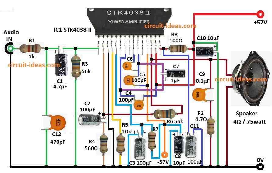
60 Watt Amplifier Circuit using IC STK4038 II give loud sound to 4 ohm speaker.
The circuit is good for home audio, public speaking and any place which need more sound.
STK4038 II is high quality audio IC with low distortion, strong power and is safe from overheat.
This article explain how it works, circuit details, and how to build it and is easy for beginners.
Circuit Working:
Parts List:
| Component | Quantity |
|---|---|
| Resistors (All resistors are 1/4 watt unless specified) | |
| 1k | 1 |
| 4.7Ω | 1 |
| 560Ω | 1 |
| 10k | 1 |
| 56k | 2 |
| 100Ω R7 and R8 | 2 |
| Capacitors | |
| Ceramic 470pF | 1 |
| Ceramic 1000pF C6 | 1 |
| Ceramic 100pF | 2 |
| Electrolytic 4.7μF | 1 |
| Electrolytic 1μF | 1 |
| Electrolytic 0.1μF | 1 |
| Electrolytic 100μF | 3 |
| Electrolytic 10μF | 2 |
| Semiconductors | |
| IC STK4038 II | 1 |
| Speaker 4Ω 75 watts | 1 |
Audio signal goes in through resistor R1 and capacitor C1.
Capacitor C12 remove high frequency noise and make input clean.
STK4038 II IC boost the signal.
Inside IC the different parts like differential amp and push-pull stage give proper gain and power.
Resistors R6, R7 and capacitors C6, C7, C5 make negative feedback by keeping circuit stable and improves the audio.
Boosted signal goes to speaker through capacitor C9.
Resistor R2 stop too much current to speaker and C9 block DC from reaching the speaker.
Capacitors C2, C3, C8, C10 help power supply stay smooth.
Max voltage STK4038 can take is +/- 57V DC.
Formulas with Calculations:
Formulas and math for 60W amp with STK4038 II:
Voltage Gain (Av):
Av = R6 / R7
56kΩ / 100Ω
= 560 gain
Coupling Capacitor Frequency (fc):
fc = 1 / (2 * π * R1 * C1)
= 1 / (2 * 3.14 * 1000 * 4.7μF)
= 33.86 Hz
This shows a good bass response.
How to Build:
To build a 60 Watt Amplifier Circuit using IC STK4038 II following are the connections steps to follow:
- Gather all the parts as shown in circuit diagram above.
- Connect pin 1 of STK4038 II to Audio IN using C1 + R1.
- Add R3 and C12 from pin 1 to GND.
- Pin 2 goes to GND through C2 + R4 in series.
- Pin 3 goes direct to GND.
- Pin 4 goes to GND through R5.
- Pin 5 goes to GND using C3 and also connect R7 between pin 5 and C3.
- Connect C8 between –57V and GND.
- Pin 7 connect to pin 10 with C7.
- Pin 9 connect to pin 10 and pin 12 using C5 and C6.
- Pin 12 goes to –57V supply.
- Pin 13 goes to one end of 4Ω speaker and other end to GND.
- Also from pin 13 connect R6 to pin 4 and C2.
- Connect C9 + R2 from pin 13 to GND.
- Pin 14 goes to +57V.
- Pin 15 connect via R8 also add C10 from +57V to GND.
- Add C11 between pin 15 and GND.
Conclusion:
This 60 Watt Amplifier Circuit using IC STK4038 II give strong and clear sound.
It is easy to build.
This circuit is good for any sound system.
Just follow the above steps and we can make our own 60 watt amplifier circuit.
Leave a Reply