• Skip to primary navigation
  • Skip to main content
  • Skip to primary sidebar

Circuit Ideas for You

Get free circuit ideas online.

  • Home
  • Privacy Policy
  • About
Home » Smart Street Light Control Circuit

Smart Street Light Control Circuit

Last updated on 4 November 2025 by Admin-Lavi Leave a Comment

Light ON at night and light OFF in day all automatic!

All this is done with one LDR and a BC547 transistor.

This Smart Street Light Control Circuit is a easy and simple way to save energy.

There is no manual effort and no energy waste.
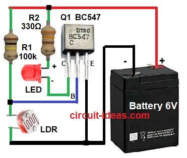
Circuit Working:

Smart Street Light Control Circuit Diagram

Parts List:

Component NameSpecificationQuantity
Resistors 100k 1/4 watt1
330Ω 1/4 watt1
LDR1
SemiconductorsTransistor BC547 NPN1
LED any color 5mm 20mA1
Battery 6V DC1

LDR change resistance when light change.

In bright light the resistance go low.

In dark the resistance go high.

LDR and resistor R1 make voltage divider.

This voltage go to base of transistor BC547.

When light fall the base voltage goes low.

Transistor does no work and LED goes OFF.

When dark come then base voltage is high.

Transistor get bias and turns ON.

And with this LED glows automatic.

Formula with Calculation:

Base current (Ib) = (Vb – Vbe) / R1

Collector current (Ic) = β × Ib

Assume transistor gain β = 100, Vbe = 0.7V.

If voltage at base is around 0.7V or more then transistor turns ON.

LED current = V / R2 = 6V / 330Ω = 18mA approx.

This is safe for LED.

How to Build:

To build a Smart Street Light Control Circuit follow the below steps:

  • Take all parts as shown in circuit diagram.
  • Emitter of transistor Q1 goes to ground (0V).
  • Collector connects to negative side of LED.
  • LED positive side goes to battery positive through resistor R2.
  • Base pin connects between LDR and resistor R1.
  • R1 goes to positive terminal.
  • LDR goes to ground.
  • Power supply is +6V battery.

Conclusion:

This Smart Street Light Control Circuit works automatic.

Light turns ON at night and OFF in day.

No need to press switch.

It saves power and time.

Good for school and home projects.

Easy to make and works well with LDR and BC547.

References:

BC547 & LDR with multiple LED’s

Filed Under: LDR Circuits, LED and Lamps, Transistor Circuits

About Admin-Lavi

Lavi is a B.Tech electronics engineer with a passion for designing new electronic circuits. Do you have questions regarding the circuit diagrams presented on this blog? Feel free to comment and solve your queries with quick replies

Previous Post: « Obstacle Detection Circuit with 555 Timer and Ultrasonic Sensor
Next Post: Automatic Street Light Circuit using Arduino »

Reader Interactions

Leave a Reply Cancel reply

Your email address will not be published. Required fields are marked *

Primary Sidebar


Categories

  • Alarm Circuits (35)
  • Amplifier Circuits (67)
  • Arduino Projects (66)
  • Audio Circuits (101)
  • Automobile Circuits (19)
  • Battery Charger Circuits (54)
  • Free Energy (13)
  • Heater and Temperature Controllers (11)
  • High Voltage (1)
  • Indicator Circuits (44)
  • Inverter Circuits (16)
  • LDR Circuits (24)
  • LED and Lamps (131)
  • Meters and Testers (30)
  • Motor Controllers (19)
  • Oscillator Circuits (35)
  • Power Supply Circuits (94)
  • Remote Control Circuits (8)
  • Security and Protection (26)
  • Sensors and Detectors (100)
  • Solar Circuits (23)
  • Timer Circuits (33)
  • Transistor Circuits (68)
  • Transmitter Circuit (15)
  • Tutorials (8)
  • Water Level Controller (4)

Recent Posts

  • IR Transmitter and Receiver Circuit using 555 and 4017 IC
  • Automatic Street Light Circuit using Arduino
  • Smart Street Light Control Circuit
  • Obstacle Detection Circuit with 555 Timer and Ultrasonic Sensor
  • Digital Dice Circuit using Arduino Uno

Recent Comments

  1. Henrik Arboe Jensen on Adjustable Voltage, Current Power Supply Circuit using Transistor 2N3055
  2. Admin-Lavi on FM Transmitter Circuit (100 meters range)
  3. DEVINDER SINGH on FM Transmitter Circuit (100 meters range)
  4. Admin-Lavi on Constant Voltage, Constant Current Battery Charger Circuit
  5. Bill on Constant Voltage, Constant Current Battery Charger Circuit

Copyright © 2025 | New Circuit Ideas