This mini condenser microphone amplifier circuit is a low cost project that strengthens the weak signal from a condenser microphone to produce a clear output; further it improves the microphones voice signal and provides good audio gain.
The circuit works with a small 9V battery and does not require an IC, so anyone can build it at home, it is also ideal for beginners who want to learn about audio electronics.
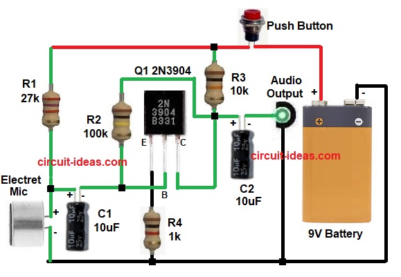
Circuit Working:
Parts List:
| Components | Values | Quantity |
|---|---|---|
| Resistors ( All resistors are 1/4 watt) | 27k, 10k, 100k, 1k | 1 each |
| Capacitors | Electrolytic 10uF 25V | 2 |
| Semiconductors | Transistor 2N3904 | 1 |
| Electret Condenser Mic | 1 | |
| SPST Switch | 1 | |
| 9V Battery | 1 |
The condenser microphone converts sound into small electrical signal, then R1 provides bias voltage to the microphone and C1 blocks DC and passes only audio signal to transistor base.
After that, Q1 works as a common emitter amplifier, R2 gives feedback and stabilizes gain and R3 acts as collector load resistor and then R4 sets emitter current and stabilizes transistor operation.
The collector of Q1 provides the amplified signal, and C2 blocks the DC component and passes the audio signal to the output and also we can connect this output to an amplifier or recorder.
How to Build:
To build a Mini Condenser Microphone Amplifier Circuit follow the below connection steps:
- First, Q1 base pin connect to C1 negative and R2 one side.
- After that, Q1 collector pin connect where R2, R3 and C2 positive meet and Q1 emitter pin connect to R4 and ground.
- Now R1 one side connect to 9V positive and R1 other side connect to MIC positive.
- Also, R2 one side connect to Q1 base and R2 other side connect to Q1 collector.
- Then R3 one side connect to 9V positive through switch S1 and R3 other side connect to Q1 collector.
- Further, R4 one side connect to Q1 emitter and R4 other side connect to ground.
- Finally, C1 positive connect between MIC positive and R1 and C1 negative connect to Q1 base and C2 positive connect to Q1 collector and C2 negative connect to output.
Conclusion:
To conclude, this is easy Mini Condenser Microphone Amplifier Circuit, it uses minimum components and low cost parts; also the circuit gives good gain for condenser microphone.
Moreover, it is useful for audio projects and experiments and also beginners can easily build and test this circuit.
Leave a Reply