Time control is very important in our daily life, sometimes we do forget small tasks; so this 5 To 20 Minutes Alarm Timer Circuit helps us remember.
This circuit provides an alarm after a preset time by using the popular IC 555 timer.
We can select a delay from 5 to 20 minutes by pressing the start and reset buttons, and the buzzer sounds automatically when the selected time expires.
The circuit is simple and with low cost and it works on 9V battery which is very easy to build and is best for beginners and hobby projects.
Circuit Working:
Parts List:
| Components | Values | Quantity |
|---|---|---|
| Resistors | 22k, 470k | 2 |
| 1M, 1.5M, 2.2M | 1 each | |
| Capacitors | Electrolytic 470uF 25V | 2 |
| Ceramic 0.1uF | 2 | |
| Semiconductors | Timer IC 555 | 1 |
| Buzzer 9V | 1 | |
| Battery 9V | 1 | |
| Push Button Switch | 2 | |
| ON OFF Switch SPST | 2 | |
| Toggle switch 3 pin | 4 |
Circuit working for 5 Minutes Timer:
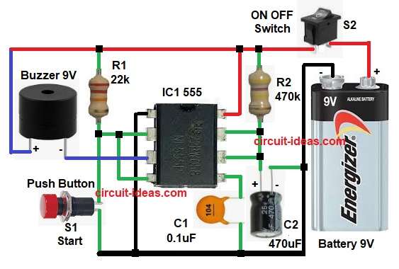
To begin with, the above IC 555 circuit is in monostable mode.
When the power is ON, the circuit remains inactive and when we press the S1 start button, pin 2 goes LOW and triggers the IC1 555. As a result, output pin 3 goes HIGH and turns the buzzer ON.
Then capacitor C2 starts charging through resistor R2 and after set time is over the capacitor becomes fully charged; after that, output pin 3 goes LOW and buzzer turns OFF automatically.
Finally, timer resets itself and waits for next start.

Circuit Working for 5 to 20 Minutes Timer:
The above circuit also operates in monostable mode, and we can use different resistors to change the timing.
Selector switches S3 to S6 select different resistors and each resistor gives different delay time.
- 5 minutes uses 470k resistor
- 10 minutes uses 1M resistor
- 15 minutes uses 1.5M resistor
- 20 minutes uses 2.2M resistor
When we press the S2 start button, the timer starts, the selected resistor controls the charging speed of the capacitor, and after the selected time elapses, the output goes LOW and the buzzer stops automatically.
Formulas:
Timer Formula:
Time delay formula for IC 555 monostable mode
T = 1.1 x R x C
where,
- T is the time in seconds
- R is the resistance in ohms
- C is the capacitance in farads
How to Build:
To build a 5 To 20 Minutes Alarm Timer Circuit following are the steps we need to follow for connections:
IC1 555 Pin Connection for 5 Minutes Timer Circuit:
- First, assemble all the parts as shown in circuit diagram.
- Next, pin 1 ground connect to battery negative.
- Then pin 2 trigger and pin 4 reset connect between S1 start push button and resistor R1
- After that, pin 3 output connect to buzzer negative and positive of buzzer connect to positive supply.
- Now pin 5 control voltage connect to C1 capacitor and GND.
- Also, pin 6 threshold connect to positive terminal of C1 capacitor.
- Further, pin 7 discharge connect to R2 resistor.
- Finally, pin 8 VCC connect to battery positive and then connect switch S2 to positive of 9V battery
IC2 555 Pin Connection for 5 to 20 Minutes Alarm Timer Circuit:
- First, pin 1 ground connect to battery negative.
- Next, pin 2 trigger connect between positive supply and resistor R1
- Now pin 3 output connect to buzzer negative and positive terminal connect to positive supply.
- Then pin 4 reset connect to one end of S2 start switch and other end of switch to GND.
- Also, pin 5 control voltage connect to C1 capacitor and ground.
- Further, pin 6 threshold and pin 7 discharge connect to positive terminal of timing capacitor C2 and GND.
- Finally, pin 8 VCC connect to battery positive and then connect resistor R2 to R5 in series with S3 to S6 switch from positive supply to pin 6 and 7 of IC2
Conclusion:
To conclude, the 5 to 20 Minutes Alarm Timer Circuit using IC 555 is a very useful project, it is simple and reliable, and we can easily change the timing by adjusting the resistors.
Also, this circuit is ideal for beginners and students, and they can use it in many everyday electronic projects.

Leave a Reply