This AF Signal Preamplifier Circuit with LM741 IC operational amplifier which boost very weak audio signal to strong level; also it uses single 12V power supply.
Furthermore, this preamp circuit work for microphone, AF input, audio player low output and weak signal source.
We can use LM741 IC because it is cheap and easily available and it gives good voltage gain for small audio signals and also this circuit is simple and good for beginner electronics projects.
Finally, this circuit remove noise and improve signal quality before sending to main amplifier.
Circuit Working:
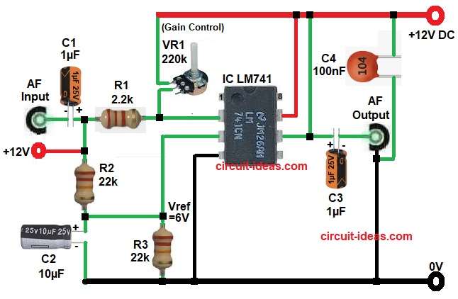
Parts List:
| Components | Values | Quantity |
|---|---|---|
| Resistors | 2.2k | 1 |
| 22k | 2 | |
| Potentiometer 220k | 1 | |
| Capacitors | Electrolytic 1µF 25V | 2 |
| Electrolytic 10µF 25V | 1 | |
| Ceramic 100nF | 1 | |
| Semiconductors | IC LM741 Op-Amp | 1 |
| Power Supply +12V DC | 1 |
To begin with, this circuit use LM741 op-amp in single supply 12V mode.
So we created a mid voltage reference around 6V using R2 and R3 divider and this mid point is very important because LM741 cannot handle very small single supply signals properly without it.
First, 12V supply go to circuit and then R2 and R3 divide voltage and make around 6V reference point.
C2 smooth this reference and remove noise, so voltage become stable.
Next, AF input signal enter through capacitor C1 and this capacitor block DC and allow only AC audio signal.
Then signal go through R1 and reach pin 2 (inverting input), so small audio signal enter op-amp input stage.
Now main important part is feedback, potentiometer VR1 connect from output (pin 6) back to input (pin 2).
So output signal come back to input side and this feedback decide how much signal will amplify.
If R4 value increase → gain increases and if R4 value decrease → gain decrease
So we get smooth gain control using VR1 pot.
When input signal come, op-amp try to make both pins equal and so it increase output voltage at pin 6.
Finally output come from pin 6 and this output still has DC level (around mid supply).
Then pure AC audio signal go to AF OUT terminal; so final output become strong audio signal.
How to Build:
To build a AF Signal Preamplifier Circuit with LM741 IC follow the below steps for connection:
- Start, the circuit by gathering all the circuit parts.
- First, give +12V to pin 7 and then connect ground to pin 4.
- After that, feed audio signal with C1 capacitor through pin 2.
- Next, connect feedback resistors R1 and VR1 between pin 6 and pin 2.
- Then take output from pin 6 through C3 capacitor.
- Also, resistors R2 and R3 set proper input level + stable bias.
- Capacitor C2 cleans the signal and only audio passes.
- Finally, pot VR1 adjusts input sensitivity / gain.
Conclusion:
Overall, this AF Signal Preamplifier Circuit with LM741 IC is simple and useful circuit which improve weak audio signal to strong level easily.
Circuit also uses minimum components and low cost design and works good for microphone preamp, audio booster and small signal amplifier stage.
IC LM741 make stable gain and VR1 give control on output level; so this circuit is very useful for basic audio electronics projects and learning purpose.
Finally, if we build carefully then we get clear and strong audio output without much distortion.
Leave a Reply