This circuit for Spy Phone Bug Transmitter Circuit is like small secret listening thing; It can listen and record phone talk which people do not know.
Also, this type of device is called a bug or transmitter because it can spy on peoples conversations, so people should not use it for illegal or unethical purposes.
Moreover, in some country this circuit maybe not be legal, so check in your area before trying this circuit.
Circuit Working:
Parts List:
| Components | Values | Quantity |
|---|---|---|
| Resistors | All resistors are 1/4 watt unless specified | |
| 47k | 3 | |
| 100Ω | 1 | |
| 22k | 1 | |
| 1M | 1 | |
| Preset 100k | 1 | |
| Capacitors | Ceramic 0.01μF | 1 |
| Ceramic 330pF | 1 | |
| Ceramic 5.6pF | 1 | |
| Ceramic 10pF | 1 | |
| Ceramic 0.22μF | 1 | |
| Trimmer 50pF | 1 | |
| Semiconductors | Transistors BC547 | 2 |
| Transistor BF494 | 1 | |
| Diodes 1N4007 | 1 | |
| Zener Diode 400mA 24V | 1 | |
| Coil L1 is built by winding 45 turns of 35 swg, super enameled copper wire over a 1M 1W CFR resistor | 1 | |
| Coil L2 is built by winding 3 turns of 21 swg, super enameled copper wire over a 12mm diameter air core | 1 | |
| Antenna | 1 |
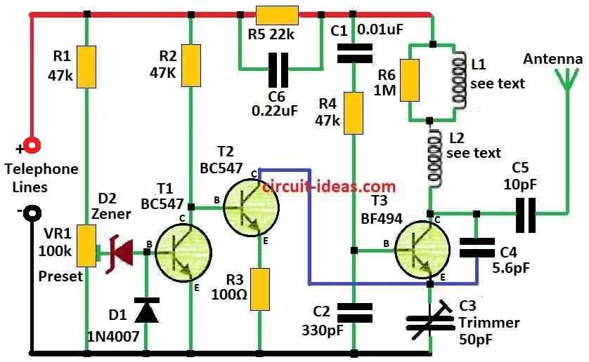
This phone bug circuit works like a wireless audio transmitter that listens to phone calls; as this circuit does not require a battery because it draws power from the phone line, which saves space and cost.
Also, the circuit consumes very little power while operating efficiently, the small 3.75 × 5 cm board makes it easy to install inside a phone box.
Circuit has two parts: FM transmitter and auto switch.
Auto switch parts are R1 to R3, VR1, T1, T2, D1, Zener D2; VR1 and R1 make voltage divider from 0 to 32V from 48V line.
If VR1 rises above 24.7V, the Zener diode breaks down, T1 turns ON and T2 turns OFF.
When someone picks up the phone, the line voltage drops to 11V, causing T2 to turn ON, T1 to turn OFF, and supply DC voltage to T3.
Also, T3 and L1 and others make low power FM transmitter and T2 is a switch and T3 is RF oscillator.
Furthermore, phone audio changes signal and antenna sends RF and lastly FM radio far away can hear the call.
Formula:
Spy phone bug transmitter is small device which uses radio waves (RF) to send sound without wire to other receiver after it hears sound around.
Below are some important parts and summary to make this device:
Formula and Important Points:
When the circuit uses an RF signal frequency, called the carrier frequency (fc), the oscillator circuit generates it and for a simple circuit, we can use the following formula to calculate fc:
fc = 1 / 2π√LC
where:
- L is coil inductance in henry H
- C is capacitor capacitance in farad F
Be careful, before we make or use spy bug circuit check rules in your country; rules may say if we need license then how strong signal can be and which frequency we can use.
Moreover, circuit design and part choice must follow these rules.
How to Build:
To build a Spy Phone Bug Transmitter Circuit following the below mentioned connections steps:
- First, connect transistor T1 base to one side of diode D1 other side of D1 will go to ground (GND).
- Then connect collector of T1 to base of T2 and emitter of T1 goes to GND.
- After that, connect emitter of T2 to GND using resistor R3.
- Next, connect collector of T2 to point where emitter of T3 and one side of capacitor C4 meet.
- Now connect collector of T3 to place where coil L2 and capacitor C4,and capacitor C5 all join.
- Then connect emitter of T3 to GND with capacitor C3.
- Connect one side of coil L1 to one side of coil L2 and other side of L1 to capacitor C1.
- Now put resistor R1 and R2 in series from plus (+) of telephone line and put resistor R5 in parallel with capacitor C6 from plus (+) of telephone line.
- Lastly, connect one side of capacitor C5 to the point where collector of T3 and C4 meet and other side of C5 connects to antenna.
Conclusion:
To conclude, this Spy Phone Bug Transmitter Circuit acts as a small hidden device that sends phone conversations through radio signals.
Therefore, the circuit does not require a battery because it draws power from the phone line, operates secretly and allows users to hear conversations through an FM radio.
Finally, use this circuit carefully because in some places it not legal.
Leave a Reply