Sometimes 7805 regulator is not enough, as it gives only around 1 amp current; however, many projects need more current for example motors, relays, LED strips and logic boards together.
Therefore, we need a simple solution, so we used an external power transistor TIP42 with 7805 IC, as this transistor boosts output current with this the voltage regulation remains stable.
Thus, this circuit is very useful because it is low-cost, easy to build, and protects the IC 7805 from overheating.
Circuit Working:
Parts List:
| Components | Values | Quantity |
|---|---|---|
| Resistors | 4.7Ω 15 watt | 1 |
| Capacitors | Electrolytic 220uF 25V, 22uF 25V | 1 each |
| Ceramic 0.1uF | 2 | |
| Semiconductors | Voltage Linear Regulator IC 7805 | 1 |
| PNP Power Transistor TIP42 | 1 | |
| Output Power Supply 5V 2A | 1 |
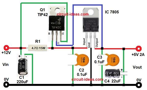
The circuit uses an IC 7805, the input DC voltage enters the circuit through the Vin terminal and capacitor C1 then removes ripple, reducing the input noise.
After that current goes through resistor R1 and this resistor controls base current.
Now transistor TIP42 starts ON and it gives extra current to the load and at the same time 7805 controls voltage and output stays at fixed 5V.
The transistor helps drive the load, allowing the IC 7805 to operate with less stress and reducing heat; finally, capacitors C2, C3, and C4 filter the noise, producing a clean and stable output voltage.
Formula with Calculation:
The calculation as per the circuit is for :
Input Voltage for Vin = 12V
Output Voltage for Vout = 5V
Voltage Drop Across R1:
Vdrop = Vin – Vout
Vdrop = 12 – 5
Vdrop = 7V
Resistor Value: R1 = 4.7 ohm
Current Through R1:
I = V / R
I = 7 / 4.7
I = 1.48 amp
Power Dissipation of R1:
P = I x I x R
P = 1.48 x 1.48 x 4.7
P = 10.3 watt
So minimum resistor power rating is 10W, but we have used 15W for safer choice.
How to Build:
To build a IC 7805 12V To 5V 2A Boost Converter Circuit follow the below steps:
- First, gather all the parts as shown in circuit diagram.
- Then start with 7805 pin 1 input connect to Vin 12V positive, connect pin 2 common ground and pin 3 output connect to output terminal.
- Also, connect capacitors C3 and C4 positive and negative to GND.
- TIP42 transistor emitter connect to Vin positive, collector connect to output line and base connect to junction of resistor R1, C1 capacitor and input pin of IC.
- Now capacitor C1 positive connect to resistor R1 one end and collector of transistor Q1 and C1 negative goes to ground.
- Finally, C2 connect between input and ground.
Notes:
- Use heat sink for transistor TIP42 and for IC 7805.
- Input voltage must not exceed 20V.
- Capacitors should be good quality.
Conclusion:
To conclude, this IC 7805 12V To 5V 2A Boost Converter Circuit is very useful, it increases current capacity of 7805 and at the same time voltage stays stable.
Also, the circuit is simple, and its components are low-cost and easily available, making it suitable for both beginners and professionals; therefore, we highly recommend this circuit for power projects.

Leave a Reply