A 5V regulated power supply is very important in electronics because it runs many digital circuits, such as microcontrollers, sensors, and logic ICs; also this 5V regulated power supply circuit using transistors provides a stable 5V DC output.
The circuit uses transistors for voltage regulation, which allows it to handle more current than IC regulators, it then converts the AC voltage into DC voltage and properly filters this direct current to reduce ripple
After that the transistors control the output voltage, so the voltage stays constant even when load changes, therefore, this circuit design is simple and is also easy to understand, hence it is very good for beginners.
Also, the components are low-cost and easily available, making the circuit ideal for lab use and learning purposes.
Circuit Working:
Parts List:
| Components | Values | Quantity |
|---|---|---|
| Resistors | 470Ω, 1k | 1 each |
| Capacitors | Electrolytic 220uF 25V | 1 |
| Electrolytic 100uF 25V | 2 | |
| Semiconductors | Transistor TIP42 | 1 |
| Transistor BD137 | 1 | |
| Zener Diode 6.2V 1W | 1 | |
| Fuse 2A, 0.5A | 2 | |
| Step Down Transformer 6.3V or 9V 2A | 1 | |
| Bridge Diodes 1N4007 | 4 | |
| On/Off Switch SPST Switch | 1 | |
| Output Power Supply 5V DC 2A | 1 |
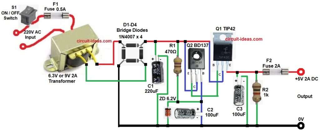
This circuit converts AC to DC and then it regulates voltage to 5V.
First, AC mains supply enters switch S1 and then fuse F1 protects the circuit; after that transformer steps down voltage and it converts 230V AC to 6.3V AC.
Next, the AC passes through bridge diodes D1 to D4, converting it into pulsating DC, then capacitor C1 filters the DC and reduces the ripple.
Now Zener diode provides reference voltage and it gives 6.2 volts fixed and then resistor R1 limits Zener current and after that transistor Q2 senses voltage.
It works as error amplifier, if voltage increases it controls Q1 and so output remains stable; next, power transistor Q1 supplies load current and it handles high current safely, as also it reduces voltage to 5V.
Finally, capacitor C3 removes noise with output DC becomes clean and thus, regulated 5V is available at output.
How to Build:
To build a 5V Regulated Power Supply Circuit using Transistors following are the steps we need to take care while connecting the circuit:
- First, start the circuit by collecting all the required components as shown in circuit diagram.
- Next, transformer primary pins connect to AC mains and secondary pins connect to bridge rectifier D1-D4.
- Then capacitor C1 positive pin goes to rectifier output and negative pin goes to ground.
- After that, Zener diode cathode goes between R1 and base circuit of Q2 and anode goes to ground.
- Now resistor R1 one side goes to rectified DC and other side goes to Zener cathode.
- Also, resistor R2 one end connects to output and other end goes to GND.
- Further, transistor Q2 BD137 base pin goes to junction of Zener diode and anode of capacitor C2, and cathode of capacitor C2 goes to GND, then emitter pin connects to base of Q1 transistor and collector pin goes to rectifier output.
- Then transistor Q1 TIP42 base pin connects to emitter of Q2, collector pin connect to rectifier output and emitter pin goes to regulated 5V output.
- Next, capacitor C3 positive side goes to output and negative side to ground.
- Finally, connect S1 switch and fuse F1 at the AC input and connect fuse F2 at +5V DC output.
Note:
- Always use heat sink for Q1.
- Check polarity of capacitors.
- Use proper fuse value.
- Do not touch AC side when powered.
- Test with multimeter before load.
Conclusion:
To conclude, this 5V Regulated Power Supply Circuit using Transistors is very useful, as it is simple and easy to build and is perfect for beginners.
Also, it gives stable output and therefore, it is good for learning electronics and so every student should try this project.

Leave a Reply