Handling 220V AC directly is very dangerous, but still we need to know mains is ON or OFF; so, this 220V AC Live Detection and Interface Circuit is useful as it solves this safety problem easily.
This circuit safely senses the mains voltage and sends a clean logic-level signal, then an optocoupler provides isolation, keeping the user safe while also protecting the low-voltage circuit.
Therefore, this circuit is good for automation work as it is also suitable for monitoring systems.
Circuit Working:
Parts List:
| Components | Values | Quantity |
|---|---|---|
| Resistors | 200k 1 watt, 5.6k 1/4 watt, 1M 1/4 watt | 1 each |
| Capacitor | Ceramic 0.1uF | 1 |
| Semiconductors | Transistor BC547 | 1 |
| Optocoupler IC 4N35 | 1 | |
| Diode 1N4001 | 1 | |
| Power Supply 5V DC | 1 |
To begin with, the main work of this circuit is to detect AC mains supply.
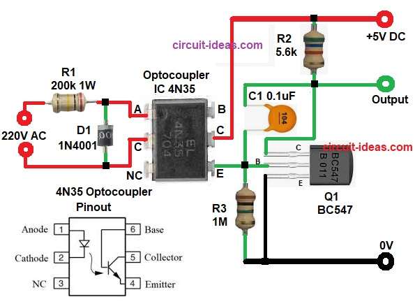
First, apply 220V AC to the input; next, the circuit converts the high-voltage AC into a safe logic signal while resistor R1 limits the current and diode D1 rectifies the AC voltage.
Now only half wave DC is available and this DC flows through optocoupler LED.
When mains power is present the optocoupler LED glows, so the internal phototransistor turns ON and because of this the current flows in low voltage side.
Next, capacitor C1 removes ripple and noise and then transistor Q1 gets base current, so transistor Q1 turns ON fully and collector output becomes HIGH or LOW which depends on circuit connection.
Thus, the circuit produces a clean logic-level output and when mains power is absent, the optocoupler LED stays OFF, so the phototransistor also remains OFF.
Finally, transistor Q1 turns OFF and the output changes state by indicating the mains power failure.
How to Build:
To build a 220V AC Live Detection and Interface Circuit follow the below steps for connection:
- First, start the circuit by collecting all the circuit parts as shown in circuit diagram above.
- Then start with optocoupler Input side pin 1 anode connect to R1 and D1 cathode.
- After that, pin 2 cathode connect to anode of diode D1.
- Now optocoupler output side pin 4 emitter connect to base of transistor Q1 through capacitor C1 and pin 5 collector connect to +5V DC through one end of resistor R2.
- Next, transistor Q1 BC547 emitter pin connects to ground and base connect to optocoupler emitter pin 4 through capacitor C1 and also collector connect to output point and R2 resistor.
- Further, R1 connect between AC live and diode cathode and R2 connect between +5V and output.
- Lastly, R3 connect between transistor base and ground.
Conclusion:
To conclude, this 220V AC Live Detection and Interface Circuit provides safe mains detection, also, it uses simple components in which optocoupler ensures isolation and transistor provides strong output.
Therefore, it is reliable and cost effective and is ideal for microcontroller interfacing.

Leave a Reply