Today electronic sound circuits are very popular among the young generation; hence, one such circuit which will benefit the beginners in electronic is a Simple Drummer Sound Circuit using IC 555.
This circuit uses the IC 555 timer, which offers a low-cost, readily available solution for sound and timing projects, also its simple design makes this project ideal for beginners.
Also, this circuit helps musicians practice with a steady, constant rhythm, also it produces drum-like sounds through the speaker, and users can adjust the sound frequency.
Therefore, this circuit is good for learning audio basics.
Circuit Working:
Parts List:
| Components | Values | Quantity |
|---|---|---|
| Resistors | 1.2k 1/4 watt | 1 |
| Potentiometer 100k | 1 | |
| Capacitors | Electrolytic C1-C2 10µF 25V, C3-C4 22µF 25V | 2 each |
| Semiconductors | 555 Timer IC | 1 |
| Loud Speaker 8 Ohm | 1 | |
| 9V Power supply / 9V battery | 1 |
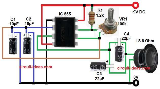
First, 9V power supply given to the circuit and this circuit built around IC 555, which connected in astable mode and this astable mode produces continuous pulses.
These pulses generate sound at output and the frequency depends on resistor and capacitor values, also VR1 used to adjust the sound tone.
Pin 8 and pin 4 of IC get positive supply and pin 1 connected to ground and then the capacitor C1 and C2 start charging and they charge through resistor R1 and VR1.
When voltage reaches two-third of supply then IC changes the state and now capacitor discharges through VR1 and this charging and discharging repeats continuously.
Therefore, square wave generated at pin 3.
Next, output pulses pass through capacitors C3 and C4 and these capacitors block DC component, but only AC signal goes to the speaker, so speaker produces drum like sound.
Therefore, rotating VR1 changes the frequency and produces different drum sounds.
How to Build:
To build a Simple Drummer Sound Circuit using IC 555 follow the below connection steps:
- First, start gathering all the parts as shown in circuit diagram.
- Then start with IC pin 1 which goes to Ground.
- Pin 2 connect to junction of VR1 and capacitor C1 and C2.
- Pin 3 connects to capacitors C3 and C4 and then connect to one end of speaker and other end of speaker will go the GND.
- Pin 4 connect directly to VCC.
- Pin 6 connect to same point as pin 2.
- Pin 7 connect between R1 and VR1 junction.
- Lastly, pin 8 connect to +9V supply.
Conclusion:
To conclude, this Simple Drummer Sound Circuit using IC 555 is very useful project, as it helps to understand IC 555 working as it produces adjustable drum sound.
Moreover, this low-cost circuit is easy to build, making it ideal for beginners who want to learn the basics of sound generation.

Leave a Reply