First of all, strobe light is a light which blinks very fast, it goes ON and OFF again and again, because of this it looks very attractive.
Nowadays, people use strobe lights in many applications, including party lighting, emergency signals, warning lights, and educational projects.
In this LED Strobe Light Circuit using Arduino, the Arduino board controls the blinking speed, while a transistor safely drives the LED.
Also, the variable resistor lets us adjust the blinking speed easily, making this simple circuit an excellent project for beginners.
Arduino Code:
int potPin = A0;
int ledPin = 12;
int potValue;
int delayTime;

void setup()
{
pinMode(ledPin, OUTPUT);
}

void loop()
{
potValue = analogRead(potPin);
delayTime = map(potValue, 0, 1023, 50, 1000);

digitalWrite(ledPin, HIGH);
delay(delayTime);

digitalWrite(ledPin, LOW);
delay(delayTime);
}
Code Explanation:
- First, potPin set to A0.
- This reads VR1 value.
- Next, ledPin set to D12.
- This controls the LED.
- Then analogRead reads VR voltage.
- It gives value from 0 to 1023.
- After that, map function converts value.
- It changes delay between 50ms and 1000ms.
- Then LED turned ON and delay applied.
- Next, LED turned OFF and again delay applied.
- This loop runs forever.
- So, strobe effect created.
Circuit Working:
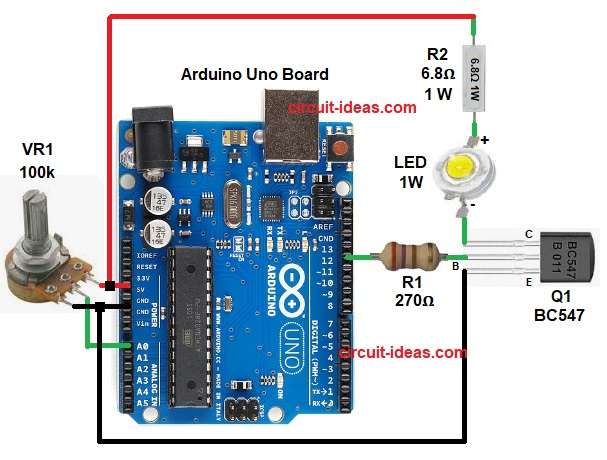
Parts List:
| Components | Values | Quantity |
|---|---|---|
| Resistors | 270Ω, 6.8Ω 1 watt | 1 each |
| Potentiometer 100k | 1 | |
| Semiconductors | Arduino Uno Board | 1 |
| Transistor | Transistor BC547 | 1 |
| Luxeon 1W High Power LED | 1 |
Circuit starts with Arduino gives power to the circuit, then VR1 creates a variable voltage and this voltage goes to Arduino analog pin A0.
Next, Arduino reads this voltage and after that the Arduino changes delay time, then Arduino sends a signal to pin D12 and this signal goes to the transistor base.
After that the transistor turns ON and so the current flows through LED and the LED glows; then the Arduino turns the pin OFF and the transistor turns OFF and the LED stops glowing.
Hence, the circuit repeats this process continuously to create the strobe light effect, and rotating VR1 changes the blinking speed..
How to Build:
To build a LED Strobe Light Circuit using Arduino follow the below steps for connection:
- First, gather all the parts as shown in circuit diagram.
- Next, connect Arduino +5V pin to the top pin of VR1, connect the bottom end of VR1 to GND and then connect the center pin of VR1 to Arduino A0 pin.
- After that connect Arduino D12 pin to resistor R1 one end and then connect the other end of R1 to the base of transistor Q1.
- Then, connect the emitter of transistor Q1 to GND, connect the collector of transistor Q1 to the cathode of LED and connect the anode of LED to resistor R2 one end and connect the other end of R2 to +5V.
- At last check all GND points are common.
Conclusion:
To conclude, this LED Strobe Light Circuit using Arduino is very simple, as it is easy to build and uses few components; also it helps to learn Arduino programming which explains analog input and digital output clearly.
Furthermore, blinking speed control, makes it interesting, which the beginners can try this project easily and also this project is good for learning and fun.

Leave a Reply