Schmitt Trigger is special type of comparator, which gives stable switching even if input signal is noisy or slow.
We can use a 555 timer IC as a Schmitt trigger and it is also used in many projects.
Furthermore, a Schmitt trigger provides two types of output: normal (non-inverting) and inverted square waves.
Next, we will learn how to make Schmitt Trigger using 555 timer IC and this timer makes inverted square wave from sine wave input.
This post for Hysteresis in Schmitt Trigger Circuit using IC 555 we will explain in detail how 555 Schmitt Trigger works, its circuit, how to build and related its formulas.
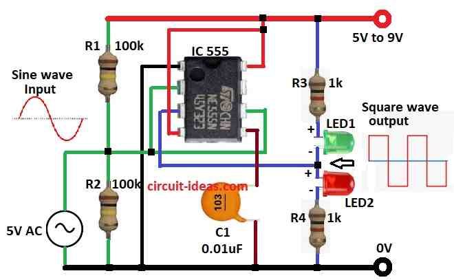
Circuit Working:
Parts List:
| Components | Values | Quantity |
|---|---|---|
| Resistors | 100k 1/4 watt | 2 |
| 1k 1/4 watt | 2 | |
| Capacitor | Ceramic 0.01μF | 1 |
| Semiconductors | IC 555 | 1 |
| LED Red 5mm 20mA | 1 | |
| LED Green 5mm 20mA | 1 |
In this circuit 555 IC has RS Flip-Flop and two inside comparators to make inverted Schmitt Trigger.
We need two same value resistors outside to build Schmitt Trigger using 555 timer and output goes to two LEDs in this setup.
Also, Trigger and threshold pins connect inside comparators and they make hysteresis between 1/3 Vcc and 2/3 Vcc.
When input goes below 1/3 Vcc then trigger comparator resets flip-flop and when input goes above 2/3 Vcc then threshold comparator sets flip-flop.
Even if input is noisy then 555 gives clear and stable output by switching only at threshold levels and then this makes Schmitt Trigger good for shaping waveforms and fixing signals.
Formulas:
To find hysteresis in 555 Schmitt Trigger circuit we use these formulas and circuit has resistor divider and capacitor to set trigger and threshold voltage.
Threshold Voltage VTH:
VTH = (R2 / (R1 + R2)) × VCC
This is voltage where output goes from LOW to HIGH.
Trigger Voltage VTL:
VTL = (R2 / (R1 + 2R2)) × VCC
This is voltage where output goes from HIGH to LOW.
Hysteresis Voltage VH:
VH = VTH − VTL
This is the difference between threshold and trigger voltages and these values help design stable Schmitt Trigger, even if signal is noisy or slow.
How to Build:
To build a Hysteresis in Schmitt Trigger Circuit using IC 555 follow below steps for connections:
- First, connect pin 1 of 555 to GND.
- Next, connect pin 2 to pin 6 and connect both to junction of R1 and R2.
- After that, connect input 5V AC signal to this junction.
- Now connect other end of R1 to VCC and R2 to GND.
- Then connect pin 3 output between 2 LEDs with R3 and R4 from VCC to GND.
- Also, connect pin 4 and pin 8 together to VCC.
- Finally, connect pin 5 to GND through capacitor C1.
Conclusion:
Overall, Hysteresis in Schmitt Trigger Circuit using IC 555 is good for cleaning noisy signals, it is easy to build with common parts.
Moreover, it gives stable output from unstable input, also this circuit shows how IC 555 can do more than just timing and how useful it is for engineers and hobby people.
Leave a Reply