• Skip to primary navigation
  • Skip to main content
  • Skip to primary sidebar

Circuit Ideas for You

Get free circuit ideas online.

  • Home
  • Privacy Policy
  • About
Home » Power Amplifier Circuit using IC TDA4935

Power Amplifier Circuit using IC TDA4935

Last updated on 5 August 2025 by Admin-Lavi Leave a Comment

Power amplifier is an useful device in audio system.

It gives power for speaker to work good.

TDA4935 is one best and is strong dual audio power amplifier IC.

People use it in bridge mode to get high power.
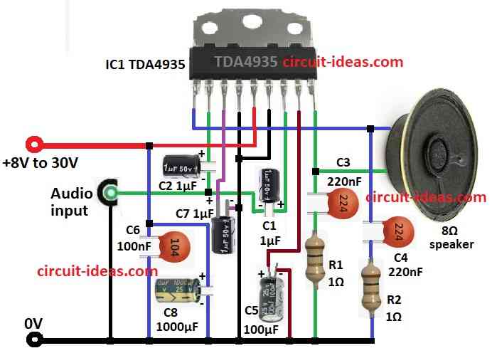
This Power Amplifier Circuit using IC TDA4935 show bridge design with TDA4935.

It power 8 ohm speaker with high output and low distortion.

Circuit Working:

Power Amplifier Circuit Diagram using IC TDA4935

Parts List:

ComponentSpecificationsQuantity
Resistor1Ω 1/4 watt2
CapacitorCeramic 220nF2
Ceramic 100nF1
Electrolytic 1µF 25 V3
Electrolytic 100µF 25 V1
Electrolytic 1000µF 25 V1
SemiconductorsIC TDA49351
Speaker 8Ω1

TDA4935 is power amplifier which make audio signal strong and it needs heat sink for cooling.

Circuit uses power from +8V to 30V DC.

Have input capacitors, feedback parts and output design for good sound.

Audio goes in at pin 7 and pin 2 through C1 and C2 which are both 1µF.

These stop DC let only AC audio pass.

For stable gain resistors R1 and R2 with 1Ω each work with capacitors C3 and C4 of 220nF, help reduce distortion and shape sound.

After amplify the sound goes to 8Ω speaker through C5 100µF.

C5 stop DC and protect speaker.

C6, C7, C8 are decoupling capacitors and they keep power clean and steady.

TDA4935 IC work in bridge mode.

Both speaker ends get signal in opposite phase and this doubles voltage and gives 4x more power than the normal design.

Formulas with Calculations:

Use these formulas to help design TDA4935 power amplifier circuit:

1. Gain (Av):

Av = Rf / Ri

where,

  • Rf is the feedback resistor
  • Ri is the input resistor

In this circuit gain is set by IC itself.

2. Output Power Pout:

Pout = Vrms² / Rload

where,

  • Vrms is the output voltage RMS
  • Rload is the speaker resistance and in this circuit it is 8Ω

3. Decoupling Capacitor Cdecouple:

C = 1 / (2π × fmin × R)

where,

  • fmin is the lowest frequency to amplify
  • R is the load resistance

4. Coupling Capacitor Ccouple:

C = 1 / (2π × fc × R)

where,

  • fc is the cut-off frequency which is below 20Hz
  • R is the input or speaker resistance

These help set power, gain and choose correct capacitor values.

How to Build:

To build a Simple Power Amplifier Circuit using IC TDA4935 follow the below mentioned steps:

  • Gather all parts as in circuit diagram.
  • Pin 1 of TDA4935 goes to one side of 8Ω speaker and also connect C4 + R2 in series to GND
  • Pin 2 connect to pin 7 through C2
  • Pin 3 connect to GND through C7
  • Pin 4 and 6 connect to GND
  • Pin 5 connect to +8V to +30V power and also connect C6 and C8 to GND
  • Pin 7 connect to audio input through C1 and GND
  • Pin 8 connect to GND through C5
  • Pin 9 connect to other side of speaker and also connect C3 + R1 in series to GND

Conclusion:

Power Amplifier Circuit using IC TDA4935 is good power amp for low ohm speaker.

It is simple in design, strong sound and is great for DIY audio.

With good heatsink it gives clear and stable sound with no noise.

Filed Under: Amplifier Circuits, Audio Circuits

About Admin-Lavi

Lavi is a B.Tech electronics engineer with a passion for designing new electronic circuits. Do you have questions regarding the circuit diagrams presented on this blog? Feel free to comment and solve your queries with quick replies

Previous Post: « 15W Class B Audio Amplifier Circuit
Next Post: Class AB Stereo Amplifier Circuit »

Reader Interactions

Leave a Reply Cancel reply

Your email address will not be published. Required fields are marked *

Primary Sidebar


Categories

  • Alarm Circuits (31)
  • Amplifier Circuits (67)
  • Arduino Projects (30)
  • Audio Circuits (93)
  • Automobile Circuits (19)
  • Battery Charger Circuits (48)
  • Free Energy (13)
  • Heater and Temperature Controllers (9)
  • High Voltage (1)
  • Indicator Circuits (38)
  • Inverter Circuits (13)
  • LDR Circuits (14)
  • LED and Lamps (114)
  • Meters and Testers (27)
  • Motor Controllers (18)
  • Oscillator Circuits (32)
  • Power Supply Circuits (91)
  • Remote Control Circuits (6)
  • Security and Protection (23)
  • Sensors and Detectors (74)
  • Solar Circuits (16)
  • Timer Circuits (28)
  • Transistor Circuits (56)
  • Transmitter Circuit (12)
  • Tutorials (4)
  • Water Level Controller (4)

Recent Posts

  • Low Power Led Flasher Circuit using Nand Gate IC
  • Two Star Flasher Circuit with 555 IC
  • Automatic Light Control Switch Circuit using IC 555
  • Ultrasonic Blind Stick Circuit using Arduino
  • Simple Humidity Level Detector Circuit

Recent Comments

  1. Admin-Lavi on Constant Voltage, Constant Current Battery Charger Circuit
  2. Bill on Constant Voltage, Constant Current Battery Charger Circuit
  3. Admin-Lavi on Long Range FM Transmitter Circuit (2km)
  4. Sina on Long Range FM Transmitter Circuit (2km)
  5. Admin-Lavi on Long Range FM Transmitter Circuit (2km)

Copyright © 2025 | New Circuit Ideas