Car battery charger help car run good by keeping battery charged, also this simple circuit uses MC78T12ABT IC which works well.
Moreover, Freescale designed this robust IC to handle high current, as it is similar to the 7812 voltage regulator, comes in a TO-3 package and can deliver up to 3A of output current.
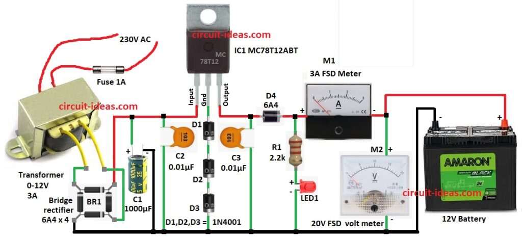
This Car Battery Charger Circuit using the MC78T12ABT IC charges a 12V lead-acid battery and allows users to monitor both the charging current and voltage.
Circuit Working:
Parts List:
| Components | Quantity |
|---|---|
| Resistor | |
| 2.2k 1/4 watt | 1 |
| Capacitors | |
| Ceramic 0.01µF | 2 |
| Electrolytic 1000µF, 25V | 1 |
| Semiconductors | |
| IC MC78T12ABT | 1 |
| IC ground diode 1N4001 | 3 |
| Output Diode 6A4 | 1 |
| Bridge rectifier diode 6A4 | 4 |
| LED Any 5mm 20mA | 1 |
| Ammeter 3A FSD | 1 |
| Voltmeter 20V FSD | 1 |
| 0-12V primary, 230V and 3A secondary step-down transformer | 1 |
| Battery 12V | 1 |
In this circuit the AC 230V from wall goes to transformer voltage which drop to safe level, then transformer gives 15V 3A from secondary winding, also this 15V goes for more processing.
Then bridge rectifier BR1 change AC to DC and output is bumpy DC, so big capacitor C1 1000µF 25V smooth it.
After that, the smooth DC goes to IC1 (MC78T12ABT), which maintains a steady 14.1V output.
Diodes D1, D2 and D3 raise the ground pin by 2.1V to achieve the 14.1V output voltage.
So 12V + 2.1V = 14.1V output, then output goes to battery through diode D4 and it stop backflow if power is OFF.
Further, R1 and LED1 show battery is charging, M1 is the ammeter which show charging current and M2 is the voltmeter which show battery voltage.
Formulas:
To make our own car battery charger with IC MC78T12ABT use these formulas:
Filter Capacitor (C1):
Ripple voltage (∆V) = I / (f × C)
where:
How to Build:
To build a Car Battery Charger Circuit using IC MC78T12ABT follow the below mentioned steps for connections and assembling:
- First, put all parts as shown in circuit diagram.
- Next, connect capacitor C2 from input pin of IC1 MC78T12ABT to GND and positive side of C2 goes to input pin and negative to GND.
- Then bridge rectifier BR1 connect one pin to 0V-12V transformer wire, bridge rectifier BR1 connect second pin to IC1 input pin, bridge rectifier BR1 connect third pin to GND and ridge rectifier BR1 connect fourth pin to second transformer wire
- Now connect fuse F1 to 230V AC input.
- Also, IC1 GND pin goes through D1, D2, D3 (in series to GND) and IC1 output pin connect to C3 and to GND.
- Further, diode D4 from IC1 output pin stops reverse current and resistor R1 and LED1 in series connect from output pin to GND which shows charging.
- Next, connect meter M1 ammeter from output pin, connect meter M2 voltmeter from output pin to GND and output pin of IC1 goes to +12V battery positive and battery negative goes to GND.
Conclusion:
To conclude, this Car Battery Charger Circuit using IC MC78T12ABT is cheap and reliable circuit, it gives steady charge and stops reverse current.
Furthermore, meters ammeter and voltmeter help check charging and also it is easy design with common parts and is good for DIY lovers.
Leave a Reply