This article show how to use LDR and a relay to make a Automatic Street Light Circuit.
Now many place uses LED street lights that turn on by itself, because people want to save energy!
To save power these lights use LDR sensor to know when dark come.
This article tell how to use LDR to make circuit that turn ON normal 230V street light at night without pressing any switch.
Circuit Working:
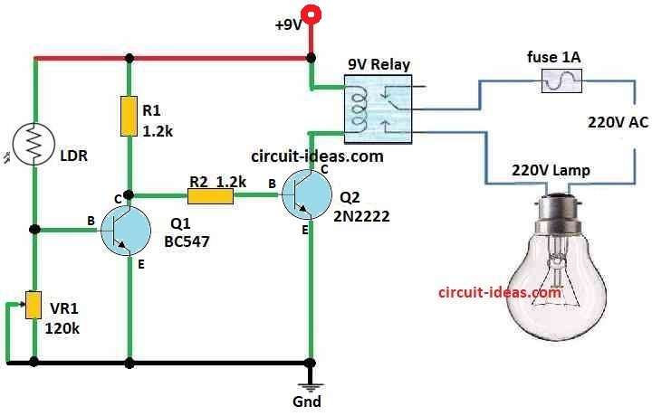
Parts List:
| Component | Value | Qty |
| Resistors | 1.2k 1/4 watt | 2 |
| Potentiometer 120k | 1 | |
| LDR Standard Value | 1 | |
| Semiconductors | Transistors BC547 and 2N2222 | 1 each |
| Relay 9V SPDT | 1 | |
| Fuse 1A | 1 | |
| Lamp 220V | 1 |
LDR is main part in our Automatic Street Light Circuit.
When light goes down LDR resistance also goes down and this make small voltage bias come to base of transistor Q1.
Because of this transistor Q1 turn ON.
But transistor Q2 does not get bias so it stays OFF.
So relay coil do not get power and it stays OFF.
When dark come with no light or very less light, LDR resistance become very high.
Now transistor Q1 turn OFF because no bias is on base.
But transistor Q2 get bias now so it turn ON and then relay coil get power and turn ON.
Formulas:
This circuit control how transistor Q1 and Q2 turn ON or OFF it uses LDR behavior to control relay coil.
Below is formula that show how LDR resistance RLDR changes with light:
RLDR = R0 * (1 + α * Illuminance)
where:
- RLDR is LDR resistance.
- R0 is LDR resistance when full dark.
- α is how sensitive the LDR is.
- Illuminance mean how much light is there.
Application and Use:
Automatic Street Light System now is very common as it saves energy and is good for street lighting.
When it become dark or light goes during power cut, then device turn ON the light to make area safe and bright.
This device is low cost and good for environment.
Conclusion:
New big idea in saving energy and auto light is Automatic Street Light Circuit using LDR.
This circuit works good and give smart way for street lighting.
It helps make future more green and better for environment.
Leave a Reply