Automatic emergency light use battery and give light when power is gone.
Lamp turns ON itself when main power fails and is good for home, office or anywhere which need extra light.
It is best to use 6V lead acid battery or 5×1.2V NiCd cells.
The design for Battery Operated Automatic Emergency Light Circuit is cheap, easy and parts are found easily.
Circuit Working:
Parts List:
| Component | Specification | Quantity |
|---|---|---|
| Resistors | 27Ω, 470Ω 1/4 watts | 2 |
| Capacitors | Ceramic 0.1µF | 2 |
| Electrolytic 1000µF 25V | 1 | |
| Semiconductors | IC 7809 | 1 |
| Transistor 2N2907 | 1 | |
| Diode 1N4007 | 3 | |
| Transformer 230V AC primary, 12-0-12V secondary 500mA | 1 | |
| Switch On/Off switch | 1 | |
| Lamp 6V | 1 | |
| Battery 6V | 1 |
Circuit uses step-down transformer and changes 230V AC to 12V AC.
Diodes D1 and D2 make DC.
IC1 7809 keep steady 9V DC and also charges the battery.
At normal time the battery charges through R1 and D3 where Q1 goes OFF and lamp is also OFF.
Power fails and battery send power through Q1 and lamp is ON.
D3 stop battery current going back to regulator.
S1 turn system ON/OFF where ON means battery is charge by keeping lamp OFF.
And OFF means lamp is on from battery.
Fuse protect circuit from damage.
Formulas with Calculations:
R1 27Ω limits battery charge.
I = (9V − 6V) / 27Ω = 3 / 27 = 0.111 A = 0.11 A
= 110 mA
This shows slow and safe charge.
R2 is base resistor 470Ω for Q1 2N2907
I_B = 6V / 470Ω = 0.012766 A = 12.77 mA
=12.7 mA
This is enough base current to turn transistor ON and light a lamp.
How to Build:
To build a Battery Operated Automatic Emergency Light Circuit following steps are required for connections of the circuit:
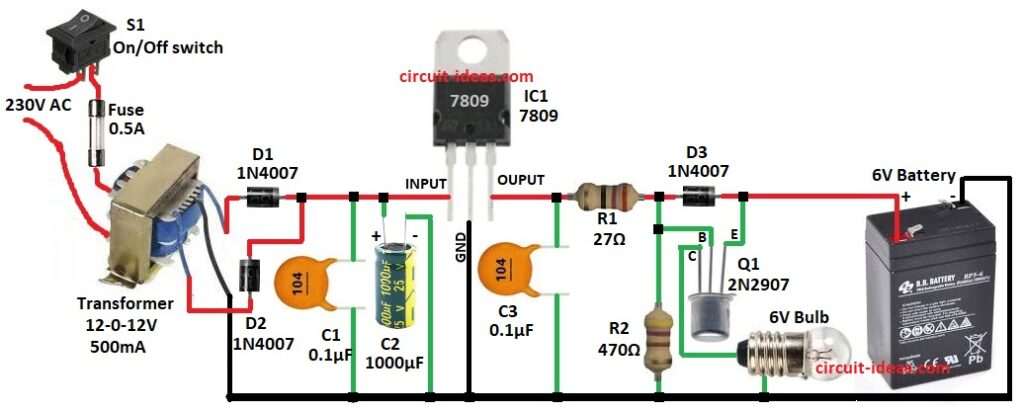
- Assemble all parts as per circuit diagram.
- Connect IC1 pin1 to positive of C2 and C2 negative connects to GND.
- IC1 pin2 GND pin connect to GND of the circuit.
- IC1 pin3 OUT pin connect to one end of C3 and C3 other end goes to GND.
- Put C1 from IC1 input to GND.
- Put R1 between IC1 OUT and anode of D1 and D1 cathode connect to Q1 emitter.
- Base of Q1 connect to junction of R1 and R2 and other end of R2 goes to GND.
- Q1 collector goes to one end of 6V lamp and lamp other end to GND.
- Put D1 and D2 across transformer secondary parallel and center wire of secondary goes to GND.
- Primary of transformer to 230V AC goes through fuse and S1 ON/OFF switch.
- 6V battery positive connects to IC1 OUT and battery negative connects to GND.
Conclusion:
This Battery Operated Automatic Emergency Light Circuit charges battery when mains power is ON.
When mains fails then transistor Q1 lets battery, power the 6V lamp automatically.
Circuit is simple with few parts and is good for backup light for emergencies.