This Simple Water Level Indicator Buzzer Circuit show how much water is there inside a tank.
It make beep sound like alarm when water goes too high or too low.
We can make it using transistor and some other small electronic parts.
It only beep when water touches two metal pieces inside the tank.
In this post it shows how to make this circuit and what good is in it and what not is not so good.
Circuit Working:
Parts List:
| Components | Value | QTY |
| Resistor | 10Ω 1/4 watt | 1 |
| Semiconductors | Transistors BC547, BC557 | 1 each |
| Speaker 8Ω | 1 | |
| Power Source +3V to 6V | 1 | |
| Water level probes Any Metal probes | 1 |
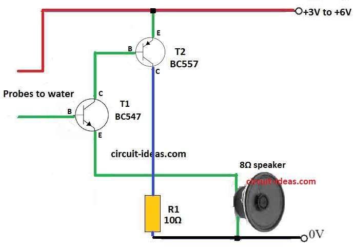
First we need to understand what parts are used and how they connect in this circuit:
- +3V power connects to emitter of BC547.
- Collector of BC557 connects to base of BC547.
BC557 Transistor:
- Collector of BC557 connects to ground using 10 ohm resistor.
Speaker:
- 8 ohm speaker connects between emitter of BC547 and ground 0V.
Water Level Probes:
- Water probes are base of BC547 and +3V power wire.
Formulas:
To make water level buzzer circuit we have used simple circuit and also used below formula.
How to find BC557 base resistor:
This resistor stop too much current from going to base of BC557 and it helps transistor work good and stay safe.
Formula:
R1 = (VCC − VBE) / IB
where:
- VCC is power and in this circuit it is 3V.
- VBE is voltage drop from base to emitter which is usually around 0.7V.
- IB is base current needed for transistor to work.
Speaker resistor to limit current:
One resistor also needed with speaker and it stop too much current going to speaker or BC547 transistor as it protect both.
Formula:
R2 = VCC / Ispeaker
where:
- VCC is 3V.
- Ispeaker is how much current speaker need which is usually 20 to 30 mA for small speaker.
These formula help to make working circuit.
But remember the real resistor values and transistor may be little different.
Check datasheet or test circuit and change if needed to make the circuit working.
Working of the Circuit:
BC547 transistor work like a switch it control how mush current move in the circuit.
When no water touch the probes the base of BC547 gets no signal and so transistor stay OFF.
BC557 transistor work like voltage divider with 10 ohm resistor.
It connect to ground and give way for current to flow when water is found between probes.
8 ohm speaker is connected between emitter of BC547 and ground.
When water touch the probes the circuit become complete.
Then current flow through BC547 and it turn ON and speaker make sound.
How to Build:
- First collect all parts we need.
- Put BC547 and BC557 transistors on PCB board.
- Connect emitter of BC547 to +3V power.
- Join base of BC547 to collector of BC557.
- Connect collector of BC557 to ground using 10 ohm resistor.
- Now connect 8 ohm speaker between emitter of BC547 and ground.
- Use +3V wire and base of BC547 as water probes.
Note:
Check all the wires and be sure there are no loose connection and circuit is connected correct.
Conclusion:
This Simple Water Level Indicator Buzzer Circuit is easy way to check water level in many uses.
If user understand how parts are connected and what each part do then they can make this circuit and use it for their own work.