This simple Current to Voltage Converter Circuit using Op-Amp helps convert small input current into easy measurable voltage output.
This circuit is very useful to measure current from sensors like photodiodes, LDR modules and other low current devices, the main work of this circuit is to change input current into proportional voltage, so we can read the value easily with a voltmeter.
The circuit uses only few components, so beginners and hobby users can build it very easily.
Circuit Working:
Parts List:
| Components | Values | Quantity |
|---|---|---|
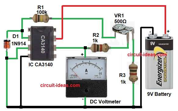
| Resistors | 100k 1/4 watt | 1 |
| 1k 1/4 watt | 2 | |
| Preset 500Ω | 1 | |
| Semiconductors | IC CA3140 | 1 |
| Diode 1N914 | 1 | |
| Battery 9V | 1 | |
| DC Voltmeter | 1 |
In this circuit, IC CA3140 works as a current to voltage converter, also called a transimpedance amplifier.
The input current Id enters the inverting pin of the op-amp which is pin 2 and the non-inverting pin is pin 3 which connects to ground.
Because of the high gain of the op-amp, pin 2 stays at almost zero voltage which we call virtual ground.
When current enters pin 2 the op-amp quickly adjusts its output at pin 6 and this output voltage flows through the feedback resistor network made by R1, R2, VR1 and R3 and because of this, the output voltage becomes directly proportional to the input current.
So in simple words: more input current = more output voltage and less input current = less output voltage
The voltmeter connected at the output shows the converted DC voltage.
How to Build:
To build a Current to Voltage Converter Circuit using Op-Amp follow the below connection steps:
- First, start the circuit by gathering all the parts as in diagram:
- Next, use IC CA3140 and connect pin 2 inverting input to the input current source which is cathode of diode sensor side.
- Then take pin 3 non-inverting input and connect this pin directly to ground.
- After that take pin 4 V- and connect this pin to ground or battery negative.
- Next, is pin 6 the output and this output voltage pin connect the voltmeter positive terminal and negative of meter goes to ground.
- Last pin 7 is V+ pin and connect this pin to +9V battery supply.
- Then take resistor R1 and connect one end to pin 2 of IC and other end connect to VR1 center pin.
- Resistor R2 connect from output pin 6 toward preset VR1 one end pin and VR1 other end pin connect to resistor R3 and ground.
- And connect diode D1 between pin 2 and pin 3 of IC.
Conclusion:
This Current to Voltage Converter Circuit using Op-Amp gives a simple and easy way to convert very small current into readable voltage.
The circuit uses few parts, gives stable output and works well for sensor-based projects and because of its simple design and easy calibration, it is a very good project for beginners, students and hobby electronics users.
Leave a Reply