This article explains about a Darkness Activated LED Circuit which is useful device that saves power, also it is energy efficient circuit because light glows only in darkness.
The circuit automatically turns the light ON at night and OFF during the day, so we never need a manual switch for daily operation; also the circuit is simple and with low cost, making it suitable for homes, gardens and pathways.
Circuit Working:
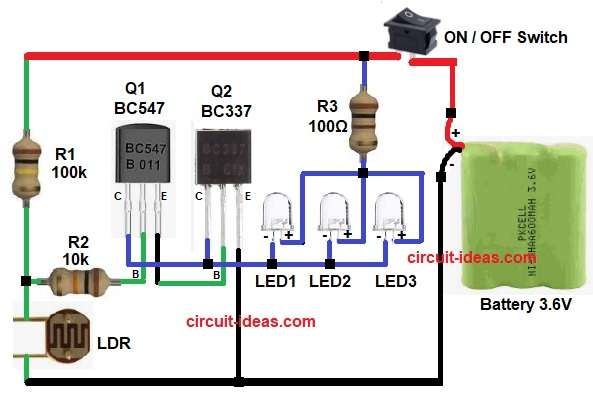
Parts List:
| Components | Values | Quantity |
|---|---|---|
| Resistors | 100k, 10k, 100Ω | 1 each |
| Standard LDR | 1 | |
| Semiconductors | Transistor BC547 | 1 |
| Transistor BC337 | 1 | |
| LED any color | 3 | |
| ON / OFF Switch | 1 | |
| Battery 3.6V DC | 1 |
To begin, connect the battery to supply power and turn ON switch S1 to activate the circuit.
During day time the light falls on LDR and so LDR resistance becomes low.
Because of this the base voltage of Q1 is low and therefore, Q1 remains OFF and then Q2 also remains OFF and so LEDs do not glow, but at night time no light falls on LDR.
So, LDR resistance becomes high and then voltage at base of Q1 increases and because of this Q1 turns ON and after that Q2 also turns ON.
Now current flows through LEDs and so LEDs glow automatically.
Thus, finally, light turns ON in dark and it turns OFF in bright light.
How to Build:
To build a Darkness Activated LED Circuit follow the below connection steps:
- First, gather all the part as shown in circuit diagram.
- Next, LDR one end goes to R1 and R2 junction and other end goes to ground
- Then R1 100k one end connects to supply positive and other end to LDR one end.
- Now R2 10k one end goes to LDR and R1 junction and other end goes to base of Q1
- Also, Q1 BC547 emitter pin connects to base of Q2, base pin connects to R and collector connects to collector of Q2 and LEDs junction.
- Further, Q2 BC337 base pin goes from emitter of Q1, emitter pin goes to ground and collector goes to negative side of LED group
- After that, LEDs anodes connected together to one end of resistor R3 and cathodes connected together to collector of Q2 and Q1
- Lastly, battery positive goes to switch S1 and battery negative to ground.
Conclusion:
To conclude, this Darkness Activated LED Circuit is very simple and is easy to build, as it uses parts which are easily available, as it takes very low power and it works properly all the time.
So, beginners can make this circuit easily which is also useful for real use; also this circuit is a good choice and is best for automatic light ON and OFF.

Leave a Reply