IC LM1875 is nice audio power amp which works very good and is very efficient.
It gives 20W power with few extra parts.
The sound is clear with low distortion and is good for many audio uses.
Circuit is good for small home audio, powered speaker, music instrument amplifiers.
In this post for Designing a 20W Audio Amplifier Circuit using IC LM1875 we will make 20W audio amplifier using LM1875.
We can see how it work, with full part calculation.
In this article we will show steps to build circuit easily.
Circuit Working:
Parts List:
| Component Type | Value/Specification | Quantity |
|---|---|---|
| Resistors (All resistors are 1/4 watt unless specified) | 180k | 1 |
| 10k | 1 | |
| 22k | 1 | |
| 1M | 1 | |
| 1k | 1 | |
| 1Ω | 1 | |
| Capacitors | Ceramic 100nF | 2 |
| Ceramic 0.22μF | 1 | |
| Electrolytic 22μF, 25V | 1 | |
| Electrolytic 1μF, 25V | 1 | |
| Electrolytic 220μF, 25V | 2 | |
| Semiconductors | IC LM1875 | 1 |
| Fuse 2A | 2 | |
| 4Ω Speaker | 1 |
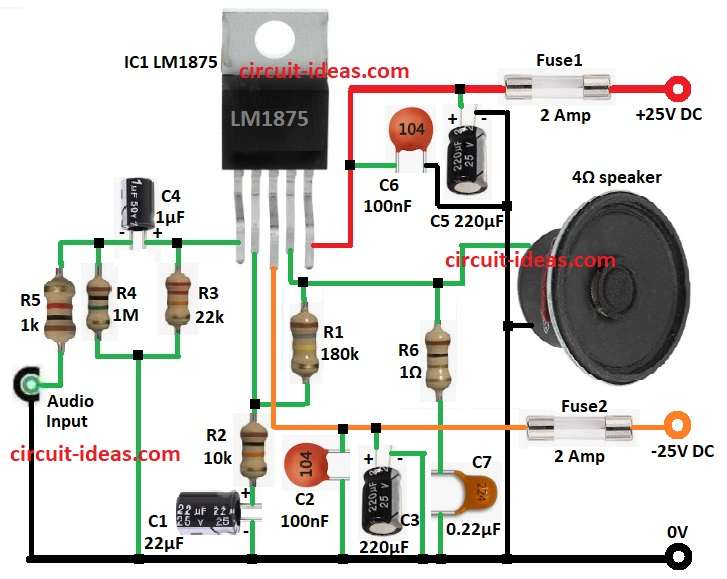
This diagram show how 20W audio amp work with LM1875 chip.
Audio signal come in through R5 and C4 to pin 1 of non-inverting input.
R4 give DC bias to this input.
Gain of amplifier uses formula with right values with gain is 19.
C2 and C3 clean noise from negative power.
C6 and C5 do same for positive power.
This keep circuit stable with less noise.
Output goes to 4 ohm speaker from pin 4.
R6 and C7 make Zobel network and help stop high frequency noise and keep amplifier stable.
F1 and F2 are fuses which protect power from too much current.
Heat sink are used to stop LM1875 from getting too hot.
Formulas with Calculations:
Formulas and Calculations for 20W Audio Amp with LM1875:
Gain = 1 + (R1 / R2)
where,
- R1 is 180k and R2 is 10k
Gain = 1 + (180k / 10k) = 19
Input Impedance:
Zin set by R5 and R4
R4 >> R5 → Zin = R5 = 1k
Output Power:
Pout = Vrms² / Rload
where,
Assume Vrms is 12.65V and Rload = 4 ohm
Pout = (12.65²) / 4 = 20W
Coupling Capacitor (C4):
Need to pass low audio frequency
Xc = 1 / (2πfC)
C = 1 / (2π × 20Hz × 1k) = 1μF
How to Build:
For Designing a 20W Audio Amplifier Circuit using IC LM1875 follow the below steps for connections and assembling:
- Pin 1 of LM1875 connects positive of side of C4
- C4 side connects one side of R5
- Other side of R5 goes to Audio input
- R3 connects between Pin 1 and positive of C4 to GND
- R4 goes between negative of C4 and R5
- Pin 2 connects one side of R2 and positive of C1
- C1 connects negative side of GND
- Pin 3 connects one side of Fuse2 and other side to –25V DC
- C2 connects from pin 3 to GND
- C3 positive side connects pin 3 and negative side goes to GND
- Pin 4 goes one side of R1 and other side of R1 goes to pin 2
- Pin 4 connects to one side of 4Ω speaker and other side goes to GND
- R6 and C7 connects from pin 4 to GND (Zobel network)
- Pin 5 connects one side of Fuse1 and other side to +25V DC
- C6 connects from pin 5 to GND
- C5 positive side connects to pin 5 and negative side connects to GND
Conclusion:
Designing a 20W Audio Amplifier Circuit using IC LM1875 is easy and works well.
It give clear sound with low noise and is good for many audio jobs.
Just follow calculations and steps to get strong and clean amplifier.
Choosing right parts and design is very important for good sound.