
Security plays a very important role in todays world, therefore electronic code locks are very useful, as this Digital Code Lock Circuit using IC 4017 is a simple; as it uses push buttons, diodes, resistors, capacitor and IC CD 4017 .
Moreover, this low cost circuit is easy to build, operates from a 9 V power supply, and provides an excellent project for students and beginners.
Circuit Working:
Parts List:
| Components | Values | Quantity |
|---|---|---|
| Resistors | 100k | 2 |
| 10k, 1k | 1 each | |
| Capacitor | Electrolytic 100uF 25V | 1 |
| Transistor BC547 | 1 | |
| IC CD 4017 | 1 | |
| Diodes 1N4007 | 6 | |
| LED any color | 1 | |
| Push Button Switch | 10 | |
| Relay 9V DC | 1 | |
| Battery 9V | 1 |
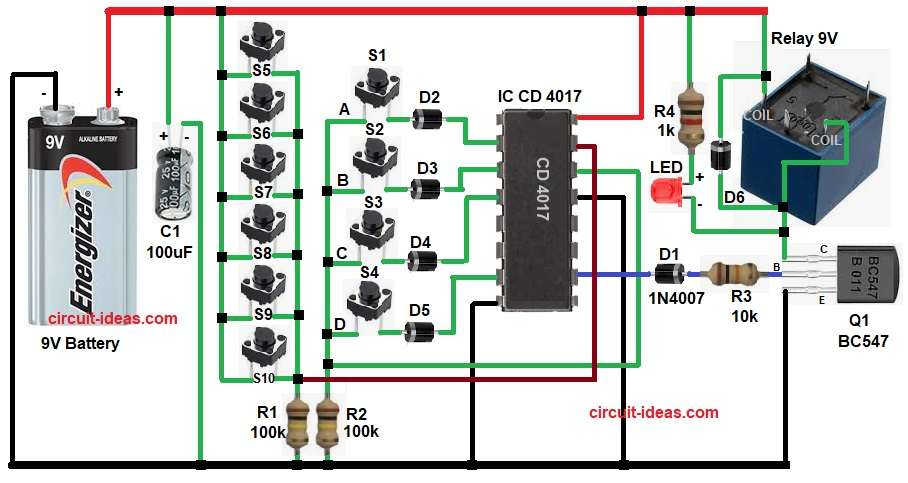
This circuit uses IC CD 4017 and it is a decade counter IC, also there are 10 push buttons with some buttons are correct keys and some buttons are wrong keys.
A transistor drives the relay, which acts as the output switch and diodes then provide logic isolation, and an LED indicates the output status.
At first, applying power resets the CD4017 to Q0; then the user must press the correct keys in sequence, and each correct key sends a clock pulse that shifts the output to the next stage.
The wrong keys connect to the reset pin, so pressing any incorrect key resets the IC, also after the user presses the last correct key, the output goes high, causing the transistor to turn ON.
The relay energizes, switches ON the load, and lights the LED to indicate the lock has opened and when we remove power, the system automatically resets itself
Code Explanation:
If my code is ABCD then:
After RESET:
Pin 3 (Q0) is HIGH then B is the start state
Press Key A:
Clock pulse applied
Output moves from Pin 3 to Pin 2
So, A = Pin 2 becomes HIGH
Press Key B:
Next, clock pulse
Output moves from Pin 2 to Pin 4
So, B = Pin 4 becomes HIGH
Press Key C:
Next, clock pulse
Output moves from Pin 4 to Pin 7
So, C = Pin 7 becomes HIGH
Press Key D:
Next, clock pulse
Output moves from Pin 7 to Pin 10
So, D = Pin 10 becomes HIGH (Relay ON)
How to Build:
To build a Digital Code Lock Circuit using IC 4017 follow the below steps:
- First, start to collect all the parts as shown in circuit diagram.
- Next, CD 4017 pin 16 connect to +9V supply.
- Then pin 8 goes to ground.
- After that, pin 14 receives the clock input, and the correct switches connect to pin 14 through diodes.
- Now pin 13 is enable pin and its connected to ground.
- Further, pin 15 reset pin and all wrong switches connect to pin 15.
- Also, output pin 3 is Q0 connects from diode D2 and switch S1.
- Next, pin 2 is Q1 connects from diode D3 and switch S2.
- Then pin 4 is Q2 connects from diode D4 and switch S3.
- Now pin 7 is Q3 connects from diode D5 and switch S4.
- Similarly, pin 10 is Q4 connects from diode D1 to base of transistor Q1 through resistor R3.
- Further, transistor Q1 base connected to R3 resistor, emitter goes to ground and collector goes to relay coil.
- Relay one side goes of coil to +9V and other side go to transistor collector.
- Then diode 1N4002 connect across relay for protection.
- Also, LED connect in series with R4 1k resistor connected parallel to relay coil.
- After that, resistor R2 connected to pin 14 of IC and GND.
- Then, push buttons 1 to 6 one end connected to positive supply and other end connected to pin 15 of IC through resistor R1 and GND.
- At last, capacitor C1 positive end connected to 9V battery positive and negative end to battery negative.
Conclusion:
To conclude, this Digital Code Lock Circuit using IC 4017 is very useful, as it is simple and reliable and it provides good security.
Moreover, it is easy to build at home and students can learn digital logic from this project and also, this circuit is perfect for basic electronic security systems.