Volume control very important in audio technology.
Digital way is more popular now and is very exact and works well.
MAX5486 chip is made for digital volume control and its design is easy to make.
This chip can adjust sound level clear and correct with digital signals.
This article for Digital Volume Control Circuit using IC MAX5486 show how to design and use volume control with MAX5486 with steps, math and tips.
Circuit Working:
Parts List:
| Component | Specification | Quantity |
|---|---|---|
| Resistors | 1k 1/4 watt | 6 |
| 1M 1/4 watt | 1 | |
| Capacitors | Ceramic 0.1μF | 4 |
| Ceramic 1μF | 1 | |
| Semiconductors | IC MAX5486 | 1 |
| Any LEDs 5mm 20mA | 6 | |
| Push-to-on switches | 4 |
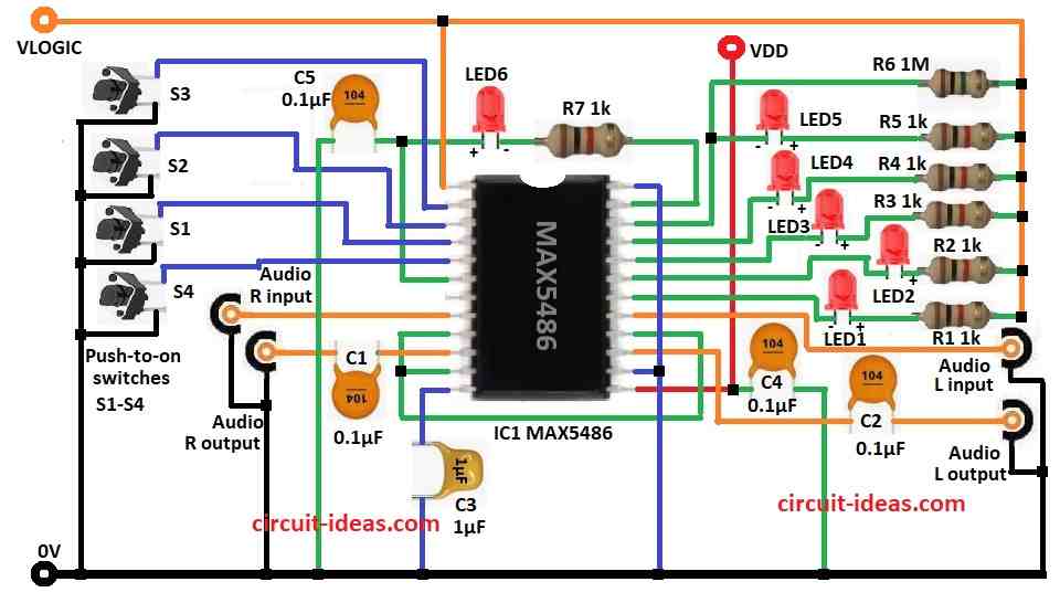
This circuit uses MAX5486 chip to control volume with digital way.
It has special digital potentiometer good for audio use.
Audio come in from Left In and Right In ports on chip.
Then sound goes out from L Output and R Output to speaker or amplifier.
C1 and C2 capacitors stop DC noise and keep sound clean.
Press button S1 the resistance goes up with sound louder.
Press button S2 the resistance goes down with sound softer.
S3 and S4 buttons mute/unmute sound by changing resistance high or to saved level.
Circuit uses two power the VDD for audio and VLOGIC for control.
C4 and C5 capacitors remove noise from power.
R7 and LED D6 show if power is ON or OFF.
LED1 to LED5 light up when buttons pressed and show which button is used.
Formulas:
Formulas for making Digital Volume Control with MAX5486:
Potentiometer Settings:
MAX5486 use log taper as it control sound level in dB like this formula:
AdB = 20 * log10 (Rout / Rtotal)
where,
- Rout is the output resistance with changing value
- Rtotal is the full resistance of potentiometer
RC Filter for C1 and C2:
Cutoff frequency (fc) is:
fc = 1 / (2 * π * R * C)
where,
- R is the input impedance like from amplifier
- C is the capacitor value
How to Build:
To build a Digital Volume Control Circuit using IC MAX5486 follow the below mentioned steps for assembling and connections:
- Collect all parts as shown in circuit diagram.
- Pin 1 of MAX5486 connects to Vlogic.
- Pin 2 connects to S3 switch and GND.
- Pin 3 connects to S2 switch and GND.
- Pin 4 goes to S1 switch and GND.
- Pin 5 goes to S4 switch and GND.
- Pin 6 connects to GND through C5 capacitor.
- Pin 8 connect to audio right input.
- Pin 9 connect to pin 11 and pin 16.
- Pin 10 connects to audio right output through C1 capacitor.
- Pin 12 goes to GND through C3 capacitor.
- Pin 13 connect to VDD and also connect C4 capacitor from same pin to GND.
- Pin 14 connects to pin 24 and also to GND.
- Pin 15 connects to audio left output through C2 capacitor.
- Pin 17 connects to audio left input.
- Pin 18 connects to Vlogic through LED1 and resistor R1.
- Pin 19 connects to Vlogic through LED2 and resistor R2.
- Pin 20 connects to Vlogic through LED3 and resistor R3.
- Pin 21 connects to Vlogic through LED4 and resistor R4.
- Pin 22 connects to Vlogic through LED5 and resistor R5 and also connect R6 resistor from pin 22 to Vlogic.
- Pin 23 connects resistor R7 and LED6 in series to Vlogic.
Conclusion:
This Digital Volume Control Circuit using IC MAX5486 is great for audio use which is simple, correct and works well.
Push buttons and LEDs make it easy with volume up, down, mute and unmute.
It uses digital potentiometer with no noise, smooth sound change and is better than old analog.
It needs few parts, easy to build, with small size and is good for home audio, speakers and devices.
MAX5486 IC shows how digital audio control is useful and powerful in today time.
Leave a Reply