In this tutorial, we will learn about simple inverter circuits that anyone can understand and build easily; also these circuits require only a few components and use no ICs or complex designs.
Just two power transistors and a transformer and it converts 12V battery power into AC supply which is good for beginners and DIY lovers and also best for learning how inverter works in real life.
Circuit Working:
Parts List:
| Components | Values | Quantity |
|---|---|---|
| Resistors | 68Ω 1/4 watt | 4 |
| Semiconductors | Transistors 2N3055 | 2 |
| Transistors MJ2955 | 2 | |
| Battery 12V | 1 | |
| Switch ON / OFF | 1 | |
| Transformer 12V-0V-12V Primary, 120V/220V Secondary | 1 |
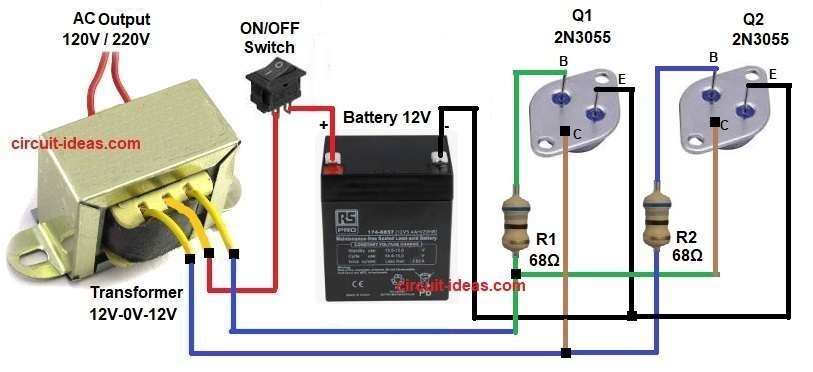
The above circuit is for Inverter Circuit using Transistors 2N3055 which uses 12V battery as power source.
Also this two 2N3055 transistors work in push-pull mode and small driver section makes square wave signal.
Then this signal switches the 2N3055 transistors ON and OFF one by one.
When one transistor turns ON then current flows through one side of transformer primary and when it turns OFF then the other transistor works.
After that, transformer changes 12V DC switching into 220V or 120V AC output and therefore, this circuit is simple and gives good power with proper heat sink.
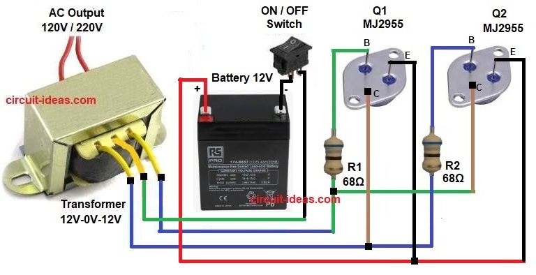
This inverter circuit uses two MJ2955 power transistors and a 12V battery, it operates as a self-oscillating astable multivibrator inverter.
Driver circuit produces square wave pulses and then this pulses switch MJ2955 transistors alternately and this MJ2955 handles high current and drives the transformer primary winding.
Transformer steps up voltage from 12V DC switching to 220V or 120V AC and hence, the circuit works cooler and smoother compared to small transistors.
Moreover, this inverter is suitable for continuous use with good cooling.
How to Build:
To build a DIY Inverter Circuit using Transistors follow the below connection steps:
- First, gather all the parts as shown in circuit diagram:
Connections for Q1 and Q2 2N3055 transistors:
- Next, emitter pin go to battery negative, collector pin go to transformer primary end, base pin go to R1 and R2 resistor 68 ohm and other end of resistor go to opposite collector
Connections for Q1 and Q2 MJ2955 transistors:
- Now emitter pin go to battery positive, collector pin go to transformer primary end, base pin go to R1 and R2 resistor 68 ohm and other end of resistor go to opposite collector.
Transformer Connection:
- Finally, center tap go to battery negative through switch, two primary ends go to collectors of transistors Q1 and Q2 and secondary end go to AC output socket
Conclusion:
Overall, this DIY Inverter Circuit using Transistors is very simple, as it is good for learning basic inverter working.
Also, its efficiency is low but acceptable
Additionally, its waveform is square wave which is not suitable for sensitive devices; in addition the circuit is best for lights, solder iron and small loads and is easy to build and we can test at home.

Leave a Reply