Electronic Mosquito Swatter Bat Circuit is very common device at home and work place.
It uses small battery and simple circuit to make big voltage.
This big voltage come on mesh net of a bat.
When mosquito or fly touches the mesh the current pass through body and insect die quickly.
Main idea is to change small DC battery power into high DC voltage using transformer and diode capacitor multiplier.
Circuit Working:
Parts List:
| Component Type | Specification | Quantity |
|---|---|---|
| Resistors (All resistors are 1/4 watt or 1/8 watt unless specified) | 36Ω | 1 |
| 680Ω | 1 | |
| 20M | 1 | |
| Capacitors | PPC 0.022 µF 630V | 3 |
| Semiconductors | Transistor 2N2222 | 1 |
| Diode1N4007 | 3 | |
| Tactile Push Button | 1 | |
| Mosquito Swatter Bat battery 4V | 1 | |
| Ferrite E core Transformer | 1 | |
| LED 3mm 20mA | 1 | |
| Racket Mesh Metal grid | 1 |
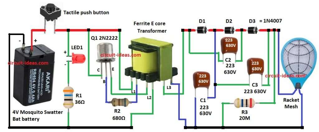
Through the above circuit diagram when we press power switch S1, transistor Q1 and transformer start working like high frequency oscillator.
Battery is 4V DC which help transformer to boost it to near 500V and above.
Then capacitor C1 to C3 and three diodes 1N4007 make ladder network.
In this step voltage is more from 500V up to about 1500V.
High voltage PPC capacitor keep the charge.
This 1500V go to racket mesh and when mosquito touch the mesh it get shock and die.
LED show battery power with ON/OFF state.
Resistor R1 can adjust to save battery life.
Transformer is ferrite E core with plastic bobbin and its winding detail are below:
L1 is 22 turns copper wire φ0.22mm
L2 is 8 turns copper wire φ0.22mm
L3 is 1400 turns copper wire φ0.08mm
Circuit is not isolated from mains so It can have dangerous high voltage.
We have to be very careful while testing or handling it.
Formulas:
Below are the formulas for Electronic Mosquito Swatter Bat Circuit:
Transformer Turns Ratio:
Output voltage = Input voltage × (Secondary turns / Primary turns).
More turns in secondary means higher voltage.
f = 1 / (2 × R × C)
This give how fast oscillation happen which is usually in kHz range.
Bigger R or C means lower frequency.
Smaller R or C means higher frequency.
Oscillator make AC signal to drive transformer.
Voltage Multiplier:
Vout = 2 × n × Vpeak
Here 3 stage multiplier give several hundred volts.
How to Build:
To build a Electronic Mosquito Swatter Bat Circuit follow the below steps for connections:
- Gather all the parts as shown in circuit diagram
- Connect positive of 4V battery to positive of the circuit and negative of 4V battery goes to GND of the circuit
- Connect switch S1 one end to positive supply of the circuit and other end to negative of the circuit
- Connect LED anode to positive of battery and cathode of LED to one end of resistor R1 and other end of resistor R1 goes to GND.
- Connect collector of transistor Q1 to positive of the circuit, emitter goes to one end of transformer L2 and other end of L2 goes to GND
- And base of Q1 goes to one end of resistor R2 and other end of R2 goes to transformer L1 one end and other goes to positive supply
- Connect transformer L3 one end to positive supply and other end goes to GND
- Diode D1 to D3 connect in series as shown in circuit diagram
- Connect capacitor C1 one end between diode D1 and D2 and other end to GND
- Connect capacitor C2 one end between diode D2 and D3 and other end to anode of diode D1
- Connect capacitor C3 from cathode of diode D3 and other end goes to one end of capacitor C1
- Connect resistor R3 one end between the junction of capacitor C3 and mesh racket and other end to GND
- Connect mesh racket one end to the junction of resistor R3 and other end connect to GND
Conclusion:
Electronic Mosquito Swatter Bat Circuit is very simple but very useful project for homes and offices.
It change small battery power into very high voltage to kill insects.
Easy to understand with low cost and many company use same idea.
With this knowledge we can repair mosquito bat or even make own mosquito racket at home.
Leave a Reply