In many 12V power supply systems, fuse protection plays an important role, a fuse protects the load and other circuit parts from overcurrent and short circuit.
However, sometimes the fuse blows and we do not know immediately, because of this the connected load stops working and so this Fuse Blown Status Indicator Circuit for 12V DC Supply helps us quickly check whether the fuse is healthy or blown.
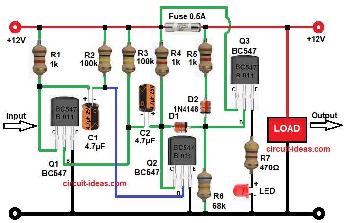
This circuit uses BC547 transistors, capacitors, resistors, diodes and one LED indicator.
When the fuse works properly, the LED remains in one state, but when the fuse blows, the transistor switching section changes the output and gives a clear visual indication.
Therefore, this circuit is useful in power supply units, battery chargers, DC control panels and small electronic systems.
Circuit Working:
Parts List:
| Components | Values | Quantity |
|---|---|---|
| Resistors (All resistors are 1/4 watt) | 1k | 3 |
| 100k | 2 | |
| 470Ω, 68k | 1 each | |
| Capacitors | Electrolytic 4.7µF 25V | 2 |
| Semiconductors | Transistor BC547 NPN | 3 |
| Diode 1N4148 | 2 | |
| LED any standard 5mm | 1 | |
| Fuse 0.5A | 1 | |
| DC Power Supply 12V | 1 |
When the 12V supply enters and passes through fuse F1 rated at 0.5A then the supply goes to the load.
Now, the transistor section Q1 and Q2 works like a simple astable multivibrator and R1, R2, R3, R4, C1 and C2 create the timing network, because of this arrangement, Q1 and Q2 switch ON and OFF one after another.
Next, D1 and D2 help in directing the signal toward transistor Q3 and this Q3 works as the output switching transistor which monitors the voltage condition across the fuse.
When the fuse is good:
When the 12V reaches the load side, where Q3 gets proper bias through R5 and D1 and as a result, Q3 turns ON.
Then current flows through R7 and LED1, so LED glows and shows that fuse is OK.
When the fuse blows:
The supply path to the load breaks and the voltage condition changes at Q3 base, then Q3 turns OFF or changes state depending on the oscillator pulse from Q1 and Q2.
As a result, LED changes status usually blinking or turning OFF and therefore, the user can easily know that the fuse has blown.
In addition, the RC network with C1 and C2 gives a pulsing indication effect, which makes the fault status more noticeable.
How to Build:
To build a Fuse Blown Status Indicator Circuit for 12V DC Supply follow the below connection steps:
- First, the circuit starts by gathering all the components as in diagram above.
- Next, start with Q1 BC547 pin 1 collector and connect to resistor R1 and capacitor C1 line.
- Pin 2 base pin connect to cross-coupled capacitor from C2 and resistor network R3.
- Pin 3 emitter connect directly to ground.
- Next, take transistor Q2 BC547 pin 1 collector and connect to resistor R4 and capacitor C2.
- Pin 2 base connect to cross-coupled capacitor from C1 and resistor R2.
- Pin 3 emitter connect to ground.
- Next, take the last transistor Q3 BC547 with pin 1 collector goes to load side and 12V sensing line.
- Pin 2 base connect through D1, D2, R5 and R6 bias network.
- Pin 3 emitter connect to R7 and LED1 to ground path.
- Capacitor C1 connect cross coupling between Q1 and Q2.
- And capacitor C2 connect cross coupling between Q2 and Q1.
- Fuse 0.5A connect in series with +12V line before load.
- Fastly, load connect positive terminal to +12V DC and connect load negative terminal to ground.
Conclusion:
This 12V DC fuse blown status indicator circuit gives simple and easy way to check fuse condition and it quickly shows if fuse is good or fuse is blown.
Also, the blinking LED indication makes fault finding very easy and fast.
The circuit uses low cost components and simple construction, so both beginners and professionals can build it easily and therefore, this circuit is very useful addition for 12V DC power supply systems.