This Header Tank Water Level Controller Circuit control water level in header tank.
It stops motor when tank is full and start motor when tank is empty.
It saves water and save electricity.
There is no need to watch tank every time.
Circuit works automatic with sensor in tank.
Circuit Working:
Parts List:
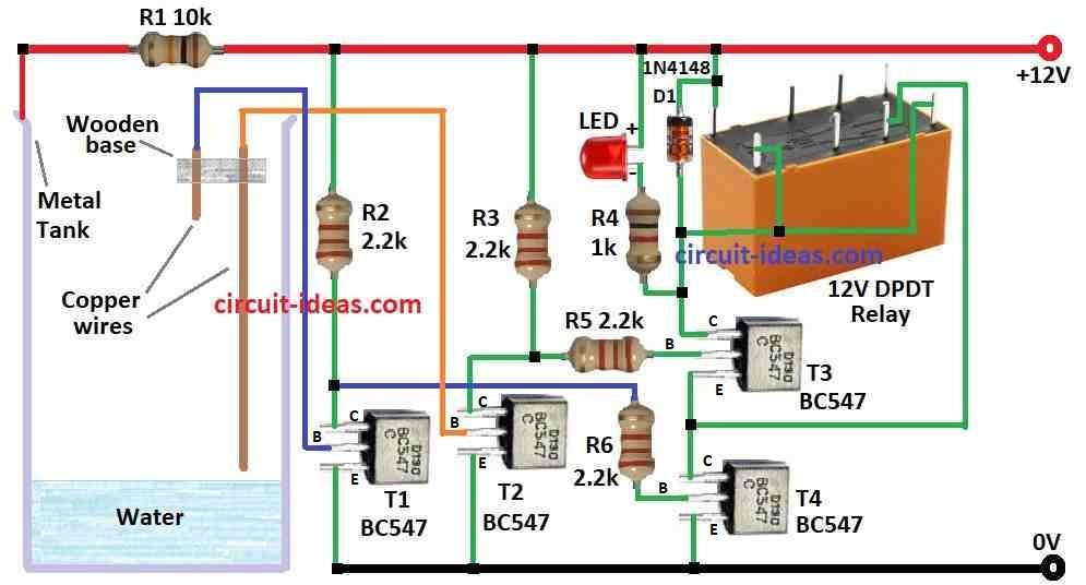
| Category | Description | Quantity |
|---|---|---|
| Resistors | 10k 1/4 watt | 1 |
| 1k 1/4 watt | 1 | |
| 2.2k 1/4 watt | 4 | |
| Semiconductors | Transistors BC547 | 4 |
| LED 5mm 20mA | 1 | |
| Diode 1N4148 | 1 | |
| 12V DPDT Relay | 1 | |
| Metal water tank | 1 | |
| Copper wires as probes | 2 |
Circuit control water pump power with transistors and relay by water level in tank.
One probe on metal tank check water level and If water level is low then probe get dry and circuit goes OFF.
No current goes to transistor T1 base so T1 stays OFF.
T2 is also OFF because no current goes to T1.
Resistor R6 gives power to T4 base and so T4 is ON.
Current flow power from R6 to T4 and then to ground.
Relay is ON and pump start.
When water rises the probe gets wet.
Current flow from power R1 to T1, probe and then to ground.
T1 is ON.
T1 takes current from T2 base so T2 gets OFF.
T4 loses power and turns OFF.
Relay gets OFF and pump stops.
Formulas:
We can make simple water level controller with transistors and relay to control pump or valve.
Formulas used:
Voltage Divider:
Find voltage at different water levels using resistors and probe.
Vout = Vin × R2 / (R1 + R2)
where,
- Vin is 12V power
- R1 is 10k resistor from 12V to probe
- R2 is resistance from probe to ground through water
How to Build:
To build a Header Tank Water Level Controller Circuit follow the below mentioned steps for connections:
- Collect all parts in circuit diagram.
- Connect collector of T1 to 12V through resistor R2.
- Connect base of T1 to left copper wire in metal tank.
- Connect emitter of T1 to ground.
- Connect collector of T2 to 12V through resistor R3.
- Connect base of T2 to right copper wire in tank.
- Connect emitter of T2 to ground.
- Connect collector of T3 to 12V through relay coil and diode D1.
- Connect base of T3 to resistor R5.
- Connect emitter of T3 to collector of T4.
- Connect collector of T4 to emitter of T3.
- Connect base of T4 to resistor R6.
- Connect emitter of T4 to ground.
- Connect LED and resistor R4 from T3 collector to 12V.
- Connect one side of tank body to 12V and other side to tank body.
- NO (normally open) pin connect to T3 collector.
- Connect pole to point between T3 emitter and T4 collector.
Safety notes:
- Circuit uses mains power which is very dangerous.
- Use good parts and wiring for safety.
- It circuit fails then it can cause water overflow or pump damage.
Conclusion:
Header Tank Water Level Controller Circuit turns pump ON/OFF based on tank water level.
It helps keep water pressure right.
This circuit is good for DIY, but better to use ready-made unit or ask electrician for safety.
References:
CONSTRUCTION OF AUTOMATIC WATER LEVEL CONTROLLER FOR BOTH OVERHEAD AND UNDERGROUND TANKS