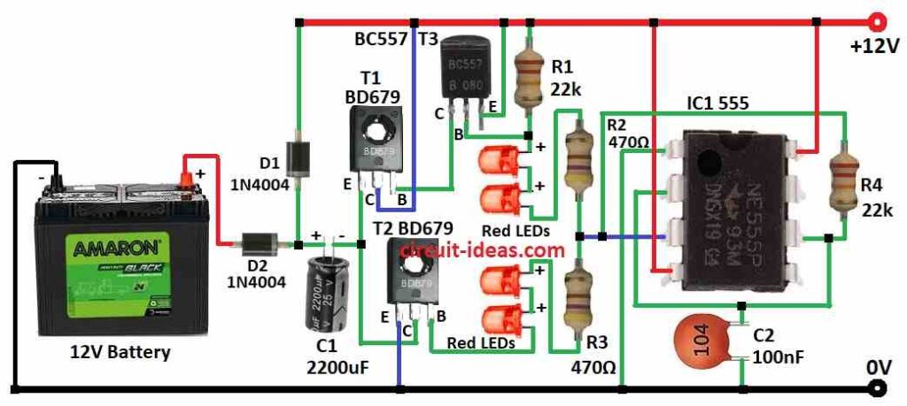
In this article the circuit starts with a 12V supply, it functions as a battery charger by employing a unique way to increase voltage over 12V and pump current into the battery.
It has particular components and makes sure transistors switch effectively to prevent overheating.
It provides a safe charging current of about 900mA even though the voltage may not reach the maximum 12V.
It is important to keep in mind the battery capacity based suggested charging timeframes and to account for some energy loss throughout the process.
Circuit Working:
Parts List:
Category | Description | Quantity | Wattage |
---|---|---|---|
Resistors | 22k, 470Ω | 2 each | 1/4 watt |
Capacitors | Ceramic 100nF | 1 | |
Electrolytic 2200μF 25V | 1 | ||
Semiconductors | IC 555 | 1 | |
Transistor BD679 | 2 | ||
Transistor BC557 | 1 | ||
LEDs | Red 5mm 20mA | 4 | |
Diodes | Diode 1N4004 | 2 | |
Other Components | Battery 12V | 1 |
Circuit working process is mentioned below:
A 12V battery cannot be charged by another 12V battery.
When the ‘floating charge’ or ‘floating voltage’ produced by the charging battery surpasses the charging voltage, the charging process comes to an end.
In order to charge a battery, the electrolytic in the circuit below uses a ‘charge pump’ configuration to provide a voltage greater than 12V.
Heatsinks are required for the diodes and transistors since the circuit generates a ‘charge current’ of around 900 mA.
The purpose of the LEDs is to stop both output transistors from going on simultaneously.
It takes more than 5V for the bottom output transistor to begin turning on, and it takes 4V for the top transistor to turn on from the positive supply.
This indicates that only when the voltage crosses a 4V mid point gap, both transistors will switch on.
This period is quite brief in our circuit, and the change happens so quickly that according to our test no current passes through the two output transistors.
The D2 diode and T2 transistor allow the electrolytic to charge to around 10V.
We require the electrolytics energy, and in our circuit the T1 transistor can supply a current of around 900mA.
However, the negative of the C1 capacitor is pulled towards the 12V supply by the T1 transistor.
The positive of the C1 capacitor is theoretically greater than 12V by 10V or roughly 9V in our situation.
This energy travels via the D2 diode to the battery.
Most batteries should not be charged more quickly than the 14 hour rate.
In essence, this indicates that a dead battery will be recharged in 14 hours.
To get the charge rate, divide the AHr capacity by 14, a 17AHr battery, for instance has to be charged at 1.2A or less.
The 2200uF capacitor can be lowered to 1000uF capacitor for batteries with smaller capacities.
About 80% of charging is efficient.
Stated differently the whole charge cycle of a battery requires the delivery of 120% of its AHr capacity.
Formulas:
You may build a simple charging circuit with IC 555 and extra parts to charge a 12V battery from a 12V source.
This is a conceptual diagram that shows how to build such a circuit with the help of formula mentioned below:
Calculating Charging Current:
Controlling the charging current that is supplied to the battery throughout the process of charging is essential in order to avoid overheating and damage.
Ohms law may be utilized to estimate it:
Charging Current Icharge:
Icharge = Vsupply − Vbattery / Rcharge
where,
- The supply voltage is represented as Vsupply 12V.
- The battery voltage Vbattery is measured at first around 12V but will rise as it charges.
- The comparable resistance in the charging route is represented by Rcharge.
Make sure resistors and transistors can withstand the charging current without overheating in order to minimize heat dissipation.
Determine the power dissipation for resistors using P = I 2 *R and, if required make sure the transistors are heat sinked.
It is strongly advised to utilize known designs or refer to comprehensive circuit diagrams and application notes related to battery charging using the IC 555 and the components indicated due to the complexity and safety concerns inherent in battery charging circuits.
Make sure you take the right safety measures to prevent harming the circuits components or the battery.
How to Build:
To Charge a 12V Battery from a 12V Supply follow the below mentioned connections components steps:
- Assemble all the components as mentioned in diagram
- Connect pin 1 of IC 555 to ground.
- Connect pin 2 on IC 555 with pin 6 of IC 555.
- Connect capacitor C2 to ground from pin 2 and pin 6 of IC 555.
- Connect pin 3 of IC 555 to resistors R2 and R3 in series.
- Connect pin 4 of IC 555 to 12V positive input supply.
- Connect pin 6 of IC 555 to pin 3 through resistor R4.
- Connect pin 8 of IC 555 to 12V positive input supply .
- Connect emitter of T1 transistor to collector of T2 transistor, connect collector of T1 transistor to 12V positive input supply, connect base of transistor T1 to collector of transistor T3.
- Connect emitter of transistor T2 to ground, connect collector of transistor T2 to emitter of transistor T1, connect base of transistor T2 to cathode of lower two red LEDs.
- Connect collector of transistor T3 to base of transistor T1, connect base of transistor T3 to anode of above 2 red LEDs, connect emitter of transistor T3 to 12V positive input supply.
- Connect resistor R1 one end between base of transistor T3 and anode of above 2 red LEDs and other end of resistor to 12V positive input supply
- Connect capacitor C1 between emitter of transistor T1 and collector of transistor T2.
- Connect one end of diode D1 between diode D2 and capacitor C1 and other end to 12V positive input supply.
- Connect anode of diode D2 to positive supply of 12V battery and cathode to capacitor C1.
- Connect negative supply of 12V battery to ground.
Safety Measures:
- In order to avoid overheating and possible damage, make sure the appropriate heatsinks are installed on these components.
- Verify again that the circuits input voltage satisfies the requirements.
- Before turning on the circuit, make sure all connections are made correctly and using the correct soldering procedures.
- It is recommended to keep an eye on the circuit while it is in operation particularly in the beginning, this enables you to detect any possible problems such as malfunction or overheating.
Conclusion:
Be cautious even though this 12V battery from a 12V supply circuit provides a means of charging a 12V battery without the need for a higher voltage source.
The use of heatsinks, appropriate component selection and adherence to safe charging procedures are essential.
References:
What happens if a 12V battery is constantly exposed to a 12V power supply?
Leave a Reply