This article for How to Convert a Speaker into a MIC Circuit shows how to turn a speaker into a microphone.
It uses the speaker to catch sound.
The sound turns into a weak signal.
A transistor circuit makes the signal stronger.
The mic wont be very clear but it is a fun way to learn how mics work.
Circuit Working:
Parts List:
| Component | Value/Type | Quantity |
|---|---|---|
| Resistors(All resistors are 1/4 watt unless specified) | ||
| 2.2k | 1 | |
| 47k | 1 | |
| Capacitors | ||
| Electrolytic 100µF 25V | 1 | |
| Semiconductors | ||
| Transistor BC547 | 1 | |
| Speaker 8Ω | 1 |
This circuit is a simple microphone amplifier that lets a speaker work like a basic mic.
But it has some limits.
Real electret microphones use a special charged part and need extra voltage to work.
Here the speakers coil acts like a variable resistor.
When sound hits the speaker it moves the cone and changes the coils resistance.
This change creates a small voltage which the transistor boosts.
How it works:
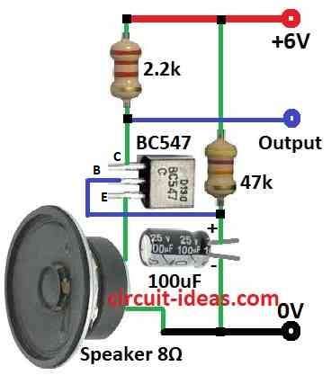
The speaker coil acts as the mic.
Sound moves the cone, changing coil resistance.
A 47k resistor sets the transistors bias current.
The 2.2k resistor and 100uF capacitor block DC from the output.
The BC547 transistor amplifies the weak signal.
Limitations:
Speakers are not made to be microphones.
Sound quality is low and may have noise or distortion.
There is no filter to remove extra noise.
This is not good for high quality audio but it is a fun way to learn how mic amplifiers work.
Formulas:
Turning a speaker into a microphone involves using it to pick up sound and then amplifying the signal.
To build this MIC circuit using a BC547 transistor we can use these basic formulas:
1. Base Resistor RB:
This resistor controls the base current IB to the transistor:
RB = (Vin − VBE) / IB
- Vin is the voltage at the transistor base
- VBE is the voltage drop from base to emitter which is usually 0.7V
- IB is the desired base current
2. Emitter Resistor RE:
This optional resistor helps keep the transistor stable:
RE = (Vsupply − VCE(sat)) / IE
- Vsupply is the power supply voltage e.g. 6V
- VCE(sat) is the voltage drop from collector to emitter when fully on
- IE is the emitter current
3. Coupling Capacitor C:
This capacitor passes the audio signal while blocking DC:
C = 1 / (2πfR)
- f is the lowest frequency we want to pass
- R is the resistance for the next stage with input impedance
Notes:
Use resistors to properly bias the BC547 transistor.
Use a capacitor to send the audio signal forward without DC.
These formulas help guide our design.
Test the circuit and tweak component values for best results.
How to Build:
How to Convert a Speaker into a MIC Circuit following are steps we need to follow for components connections:
Power Supply:
- The positive terminal of a 9V supply connects to the collector of the BC547 transistor.
Speaker as Microphone:
- The positive wire of the speaker coil connects to the emitter of the BC547.
- The negative wire of the speaker coil goes to ground.
Bias and Amplification:
- A 47k resistor connects from the base to the collector of the BC547.
- A 2.2k resistor connects between the collector and the positive power supply.
- These resistors set the bias current for the transistor.
Output Coupling:
- A 4.7k resistor connects from the base of the transistor through a 100uF capacitor.
- The negative side of the capacitor goes to ground.
- This design allows the audio signal to pass while blocking DC.
Note:
- This circuit lets a speaker work like a simple mic but sound quality is limited.
Conclusion:
Speakers are not built to pick up sound clearly, so the audio may be distorted or is uneven.
There is no filtering so background noise can be heard.
How to Convert a Speaker into a MIC Circuit is a fun learning project and is not meant for high quality sound recording.
For better results use a real microphone.