IC LM386 Based Voiceover Project Circuit is small audio project, which takes mic sound and makes it louder with LM386 chip and then sends to speaker.
We can also use this for public speaking, mix audio with mic first or talk in presentations, as IC LM386 chip is easy to use and uses less power and give good sound.
Furthermore, It gives sound power up to 1 watt and works with 5V to 12V battery.
Circuit Working:
Parts List:
| Components | Values | Quantity |
|---|---|---|
| Resistors | 10k 1/4 watt | 1 |
| Capacitors | Ceramic 0.47μF | 1 |
| Ceramic 0.1μF | 1 | |
| Electrolytic 10μF, 25V | 1 | |
| Electrolytic 470μF, 25V | 1 | |
| Semiconductors | IC LM386 | 1 |
| Diode 1N4007 | 1 | |
| Relay 12V | 1 | |
| Electret Microphone | 1 | |
| ON/OFF switch | 1 | |
| 8Ω Speaker | 1 |
To begin with, in this voiceover project audio become 200 times louder with this circuit, as it uses LM386 chip and few resistors and capacitors only.
Also, main power part has 10k resistor, two big capacitors with 10μF and 470μF and one small capacitor 0.047μF, then extra resistor and capacitor with 10k and 0.047μF makes snubber circuit which help control speaker like electromagnet.
Moreover, it works with speaker from 4Ω to 32Ω and power between 5V to 12V.
LM386 chip has 8 pins and pins 1 and 8 control the gain and we have put C2 capacitor between pin 1 and 8 and this make gain 200 times.
Hence, for testing build it on breadboard and for strong use make PCB.
Formulas:
The LM386 audio chip amplifies the microphone signal in the voiceover circuit; also it makes the mic sound louder and drives an 8Ω speaker.
Moreover, we can use the following important formula to calculate the output power:
Pout = Vpeak² / 8R
where:
- Vpeak is max voltage across speaker with almost same as power supply Vcc,
- R is speaker resistance in 8 ohms here.
This circuit is good for beginner voice amp projects, change parts and values if need better sound, different power or gain and also test and adjust circuit to work best for our needs.
How to Build:
To build a IC LM386 Based Voiceover Project Circuit follow the below mentioned steps:
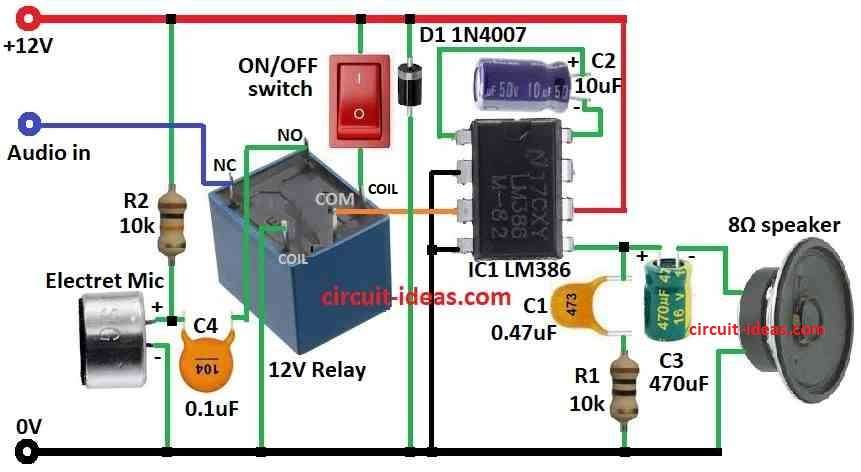
- First, put all parts as shown in circuit diagram.
- Next, connect pin 1 to pin 8 of LM386 using capacitor C2.
- After that, connect pin 2 and pin 4 to ground.
- Then connect pin 3 to common leg of 12V relay.
- Now connect pin 5 to one end of 8Ω speaker using capacitor C3 other speaker end to ground, also from pin 5 connect capacitor C1 and resistor R1 to ground.
- Also, connect pin 6 to +12V supply.
- Then connect NO (normally open) leg of relay to (+) side of MIC through capacitor C4 and (–) side of MIC to ground and connect NC (normally closed) leg of relay to audio in and also connect one coil terminal of relay to ON/OFF switch and other coil terminal to ground.
- Finally, put diode D1 from +12V to ground for protection.
Notes:
- Sound quality depends on mic and speaker quality and we can also connect other audio input using a small input jack with some changes.
Conclusion:
Overall, IC LM386 Based Voiceover Project Circuit make mic sound 200 times louder, as it is easy to build, good for DIY voice projects and works with many power supplies and speakers.
Also, this circuit is good for basic voiceover or strong mic amplifier system.
Leave a Reply